Correct connections for Pertronix Flamethrower coil?

1lastweekend

Seaman
Joined
Nov 7, 2015
Messages
52
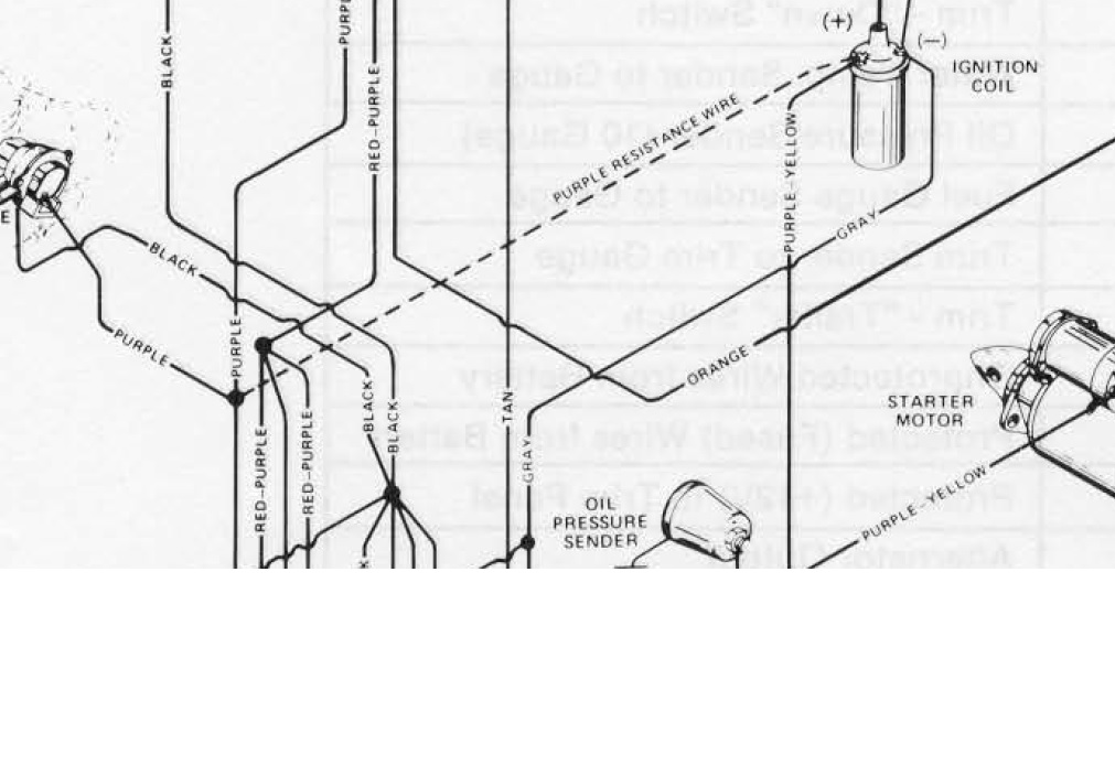
Hi I am working on installing a Pertronix 40611 3.0 ohm epoxy coil for my 1981 Mercruiser 2.5L engine, s/n 5907433. From what I have read on various forums, my OEM coil was a 1.5 ohm, but there's a simple wire swap to allow the Pertronix to function correctly. I disconnected the purple/yellow wire at the ignition switched terminal of the starter solenoid and also at the + terminal of the coil, tied it back and replaced it with a std 12ga wire at the same connection points.

According to the Pertronix instructions, where i was getting approx 6.5V at the coil with the points closed before, i should now be getting a full 12v (with the ignition keyswitch on) But I am still getting 6.5 volts!?!?! Not sure what I am doing wrong or if there is another trick- is there an internal resistor in the red wire from the harness to the + side of the coil?

OEM setup was red and purple/yellow wire to + side of coil, and grey and brown wires to - side of coil. Any help is much appreciated!
 

thumpar

Admiral
Joined
Jun 21, 2007
Messages
6,138
I did it the same way on my 2.5l. Are you getting a full 12v at the point on the solenoid you tapped into? If you get 12v there and not 12v at the coil your wire is causing resistance. Make sure you have good grounds also.
 

Bt Doctur

Supreme Mariner
Joined
Aug 29, 2004
Messages
19,236
The wire you disconnected supplies full battery power only during cranking mode, put it back. Go to the electric choke and remove that wire going to the coil. It is the resistance wire .Remove it and run a new wire from there to the positive side of the coil.
 

thumpar

Admiral
Joined
Jun 21, 2007
Messages
6,138
They are right. I had disconnected the purple (resistance) wire and ran a new wire along that path.
 

1lastweekend

Seaman
Joined
Nov 7, 2015
Messages
52
The wire you disconnected supplies full battery power only during cranking mode, put it back. Go to the electric choke and remove that wire going to the coil. It is the resistance wire .Remove it and run a new wire from there to the positive side of the coil.

I don't have an electric choke on my boat, it is the old style heat activated one.

But I did notice that the second wire on the + side of the coil is not actually red, it is purple, just was faded to what appears to be a reddish color. So if this wire is purple, it is the resistor correct? If I remove it, should I get 12v at the + side of the coil with the purple/yellow reattached?

I will check to make sure I am getting 12V at the starter solenoid as well.

Thanks all for the quick responses!
 

kenny nunez

Captain
Joined
Jun 20, 2017
Messages
3,255
Look at the schematic that the DOC sent, untape the harness and you will see the purple resistance that is soldered in, cut the purple wire at that point and solder in a new wire.
Or, run a new wire from the ignition switch to the coil and clip off the end of the resistor wire and tape it off.
 

1lastweekend

Seaman
Joined
Nov 7, 2015
Messages
52
Look at the schematic that the DOC sent, untape the harness and you will see the purple resistance that is soldered in, cut the purple wire at that point and solder in a new wire.
Or, run a new wire from the ignition switch to the coil and clip off the end of the resistor wire and tape it off.

Looks like the purple wire goes to the alternator- wouldn't it be easier to clip it there and run a new wire from the alternator to the + side of the coil?
 

thumpar

Admiral
Joined
Jun 21, 2007
Messages
6,138
Also, in case all else fails- where did you connect the other end of that purple wire to?

Thanks

I just ran a wire from where the purple wire connects to the coil. I believe it ran to the back of the starter. By just removing the purple wire you will lose all voltage unless you are cranking the engine.
 

1lastweekend

Seaman
Joined
Nov 7, 2015
Messages
52
The wire you disconnected supplies full battery power only during cranking mode, put it back. Go to the electric choke and remove that wire going to the coil. It is the resistance wire .Remove it and run a new wire from there to the positive side of the coil.

Hi just want to confirm- I traced the purple wire from the + side of the coil to the alternator. I would prefer to not cut all of the OEM tape on the harness looking for the resistor soldered in, could I just cut the wire at the alternator and run a new one from the alternator to the + side of the coil?

Thanks
 

thumpar

Admiral
Joined
Jun 21, 2007
Messages
6,138
There is no resistor soldered in. The purple wire is the resistor. Just run a new wire parallel to it.
 

1lastweekend

Seaman
Joined
Nov 7, 2015
Messages
52
Ok I am back to square one- The purple wire I thought went from the + side of the coil to the alternator must not be the same wire- when I disconnected it and added in my own wire, I got 0 volts with the keyswitch on, where I was hoping to get 12v. It looks like the same wire, but it must not be. When I hooked it all back up to OEM, I get the same 6.5 or so volts at the coil with the key on and the points closed...Does anyone know for certain where the other end of that 12v pueple esistor wire connects on the MCM120 engine?

Thanks
 

thumpar

Admiral
Joined
Jun 21, 2007
Messages
6,138
I know when I did mine I put the new wire into the the harness next to the resistor wire. It went to the back of the engine and then down by the starter. I think it was on the starter but know it was right down in that area. I cut all the covering off the harness along the way and re-wrapped it when done to look factory.
 
Top