Trim sensor wiring

Status
Not open for further replies.

Rich Novak

Petty Officer 2nd Class
Joined
Jul 22, 2012
Messages
181
I can't seem to figure ot how to wire the trim & tilt sensors
I have the manual but I am stupid.
Need. To know where they go specify.
My engine has that Mercator thing a magic on it
Please in the simplest terms
1988 sea ray Pachanga 19 ft.
4.3 v6
Also having problems adjusting the shift cables.
All video on it tried 6 in space . 7 in. None worked
Goes in forward ok no reverse tried moving stud no help.
Thanks RICHARD
 

alldodge

Moderator
Staff member
Joined
Mar 8, 2009
Messages
40,754
The limt and sender are identified on the side of them

Trim Limit switch is Port
Trim Sender is Starboard

Wiring either one makes no difference which wire goes were, only issue is don't plug switch into gauge, or sender into limit

Here is the shift cable adjustment
 

alldodge

Moderator
Staff member
Joined
Mar 8, 2009
Messages
40,754
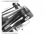
Guess I'll do one at a time. If the trim pucks are removed you should see a mark. Start with these two marks aligned and install. If during adjustment the puck will not rotate far enough and still be able to place the screws back in, remove it and rotate one of two notches in opposite direction, and re-insert

Port Side Trim limit:
With marks aligned and drive in the full down position, install limit.
Using the trim UP only (do not use trailer switch) let drive come up until it stops. Now measure between end of ram and center of nut. Distance should be 6 1/4 to 6 3/4 inches (6 1/2 +/- 1/4)
If it doesn't go far enough rotate switch counter clockwise slightly, then push UP again until it stops and re-measure.
If it goes to high, trim DOWN and rotate clockwise, then push UP until it stops and re-measure.
Slide1.JPG

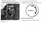
Starboard Side Trim Gauge:
With marks aligned and drive in full down position install trim sender
Turn key ON, and rotate sender until gauge needle is in about mid position. Now rotate it so that the needle just points to full down.
Tighten screws and test by trimming UP/DOWN to verify it works.
As with port side switch, if you need more adjustment room to insert crews, pull sender straight out and rotate the re-install
Slide2.JPG
 

Rich Novak

Petty Officer 2nd Class
Joined
Jul 22, 2012
Messages
181
I know what side is what. I DONT know. WhERE or what the wires connect to.
The wires where cut off from the old positions.
There for I have no guide as to where or what. They connect to.
Thank you.
 

Bondo

Moderator
Staff member
Joined
Apr 17, 2002
Messages
70,525
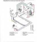
Ayuh,.... All the wirin' comes together at the transom/ trim pump,....

The sender wires go to the gauge on the dash,....
The limit switch is looped to the up solenoid,...
 

alldodge

Moderator
Staff member
Joined
Mar 8, 2009
Messages
40,754
I know what side is what. I DONT know. WhERE or what the wires connect to.
The wires where cut off from the old positions.
There for I have no guide as to where or what. They connect to.
Thank you.

Richard
I'm not the sharpest tool in the shed and sometimes I miss things, all I can say is I'm trying to understand what your asking. That said I'm seeing thre questions and just now I understand you want to know the wiring

Trim sender:
One side of sender goes to ground
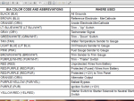
The other side goes to a Brown/White wire coming from the trim gauge

Limit switch:
one side goes to Blue/White
The other goes to Purple/White

Merc Color Codes.png

Trim wiring Merc 2012.jpg
 

achris

More fish than mountain goat
Joined
May 19, 2004
Messages
27,468
I'm going to ask an obvious question... Before I do, just know, I'm not suggesting you're stupid, but I have seen this done, so bear with me.

When you put the new senders in, did you pull the old wiring out from inside the boat? ie, was half the harness inside the gimbal housing and the other half through a small hole (that is actually plugged by the 'halves' on the wires themselves) and go though to the inside? Or were the old wires cut off inside the gimbal housing and just left?

Sorry to have to ask what appears to be a silly question, but only you can see what you have done, we can only respond by asking questions to get a clearer picture.

Chris......
 

Starmerc89

Recruit
Joined
Jun 27, 2020
Messages
1
Trim Sender (Starboard) - wiring
()One side of wiring goes to Brn/Wht(Trim Gauge on dash)
()Other side of sender wire ---> Blk (All Grounds)

Trim Limit Switch (Port) - wiring
()One side of wiring goes to Blu/Wht (Trim Up)
()One side of wiring goes to Pur/Wht (Trim "Trailer" Switch)


Install and adjust Trim Limit (Port side)
()With drive fully down and marks aligned, install limit
()Using trim up only let drive come up until it stops
()Measure 6 3/4 from center of nut to end of ram

Install and adjust Trim Gauge Sender (Starboard side)
()With drive fully down and marks aligned, install sender
()Turn key ON and rodate sender puck until gauge needle is in mid position, then rotate puck until needle is full down
()Tighten screws and test by trimming UP/DN to see if it works
 
Status
Not open for further replies.
Top