Help identify Mercury Power Trim Switch please

wcsd106

Petty Officer 2nd Class
Joined
Mar 27, 2010
Messages
182
Hi all.

Last week I brought home a new, to me, boat. Unfortunately, the power trim switch on the control handle is not functioningproperly.

The previous owner wired the trim to a toggle switch in a dumb part of the dash.

I am wanting to replace the switch and restore function to the controls as was intended. I have a couple of questions...

1. What would the mercury part number be for this switch? I think I have found it buy I'm not 100%.

2. How would you go about removing that switch? I haven't attempted to pop the switch cover off yet until i could locate a diagram.

Thanks in advance.


best image uploading site
 

Scott Danforth

Grumpy Vintage Moderator still playing with boats
Staff member
Joined
Jul 23, 2011
Messages
49,901
you pull the handle apart (should be screws underneath) to get to the switch
 

mBurns

Cadet
Joined
Apr 7, 2016
Messages
26
you may not need to replace the switch.

If you want to investigate it, there should be a wire bundle in the outboard of this handle (or under it) - 3 wires go to that switch (in my boat its red, blue, green but may be different for yours). Anyway, if you can find those wires where they come into the trim solenoid, 2 of the 3 should short together when you bump the switch one way, and 2 of the 3 the other way. they up/down share a common hot to activate the solenoid.

this could save you from having to fumble with the handle -- assuming the switch works
 

wcsd106

Petty Officer 2nd Class
Joined
Mar 27, 2010
Messages
182
you may not need to replace the switch.

If you want to investigate it, there should be a wire bundle in the outboard of this handle (or under it) - 3 wires go to that switch (in my boat its red, blue, green but may be different for yours). Anyway, if you can find those wires where they come into the trim solenoid, 2 of the 3 should short together when you bump the switch one way, and 2 of the 3 the other way. they up/down share a common hot to activate the solenoid.

this could save you from having to fumble with the handle -- assuming the switch works

Thank you for the replies someone has already tapped into those wires but they moved the power trim switch into a section of the dash that would be hard to access while underway. The switch itself feels as if the spring has gone out that provides the momentary action. I didn't see any screws on the bottom of the switch housing but I'll look again.
 

Scott Danforth

Grumpy Vintage Moderator still playing with boats
Staff member
Joined
Jul 23, 2011
Messages
49,901
most of the time, the little paddle is actuating a small switch inside the handle.
 

Chigwalla

Petty Officer 2nd Class
Joined
Jul 11, 2017
Messages
109
most of the time, the little paddle is actuating a small switch inside the handle.

While most do, on this switch the paddle is integral.

It looks like the p/n for that switch is 87-92484, which supersedes to 87-8M0046008. Prices wouldn't be relevant because I'm not in the US.

As to the wiring, red is power to the switch, green is the down circuit and blue is the up circuit. If the up circuit includes a "trailer" button, the blue wire will run to the trailer button, then become a purple wire as it goes back to the transom.

Usually, if the switch in the handle has been butchered, it's because it stopped working (generally it's the 'up' circuit). Personally, I don't even bother testing them when they don't feel normal.

The grip on top of the handle doesn't come off on these ones (unlike most). Instead, there is a set screw on the bottom of the casting that secures it to the control. The switch pulls straight out and the wires run down through the (hollow) handle.

If you're still having trouble getting the arm off the splined shaft, I can post a pic of the relevant page of the parts catalog that'll show you how it comes apart.

Can I upload pics direct on this forum or do I need to link from a 3rd party host like PhotoBucket ?
 
Last edited:

ajgraz

Lieutenant Commander
Joined
Mar 1, 2010
Messages
1,858
To the OP, the switch used in that particular control is a known weak spot. That switch is not well sealed against water intrusion from the front (paddle) side, and they are failure prone.

Add to that the wire chafing going on inside the control.

I would urge you to use a toggle, but mounted in a better location. I can post some pics of how I solved this same thing with that same control, if you have any interest in hearing me out.
 

wcsd106

Petty Officer 2nd Class
Joined
Mar 27, 2010
Messages
182
Chigwalla and ajgraz I would appreciate both of those suggestions. I would definitely like to see how to remove the arm. I would also like to hear your suggestion out, aj.
 

Chigwalla

Petty Officer 2nd Class
Joined
Jul 11, 2017
Messages
109
New member so I can't upload pics yet (one more post), but your control is easy enough to take apart.
Remove the set screw and take off the binnacle. On top of the control, you'll see where the trim wires run under the keeper and into the body of the control.
There is another set screw on the bottom of the arm (4mm or 5mm Allen key if memory serves). You can see it if you push the arm to FWD WOT.
The problem will come in getting the arm off the splines thanks to our old friend, corrosion. Some heat on the casting of the arm can help loosen it up.
Tie a piece of twine to the wires as a messenger and pull the switch out of its hole.
 

ajgraz

Lieutenant Commander
Joined
Mar 1, 2010
Messages
1,858
Here's a link to an online manual that will help you with any and all disassembly of the control. Section 4D, starting pg 142 covers this model:
http://boatinfo.no/lib/mercruiser/ma...mote.html#/142

I never liked that trim switch, not just because of failure, but also because I found that when I wrap my hand on the T-handle (the way you're supposed to in order to thumb that switch), I was constantly inadvertently jerking the whole throttle lever forward and backward with every swell and wake I hit.
(Bear in mind that I usually stand to operate, and I run HARD, sometimes in some pretty violent stuff)

As to what I did instead of replace the switch...

I used that manual to disassemble everything and get the trim switch and wiring out of the control (and inspect and lube the control's innards as a bonus). Replaced the switch in the control handle with plastic plug, Mercury part number 19-19027. I wiped off the "trim up, trim down" white screen printing on the top of the handle with Goof-Off. At that point what you've got is absolutely identical to the non T&T version of this very control.

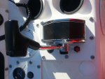
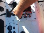
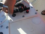
I used a Carling (on)-off-(on) toggle, with a silicone boot (for water resistance), mounted really, really close to the control (see pics). I found that to allow me to "slide" my right hand down the shaft when underway, resting my palm on top of the control's cover (a very stable way to hold that hand and steady myself while operating, BTW). In this position I can easily reach the toggle with my thumb, yet if I do need to do an emergency throttle-back I can just quickly wrap my fist around the chrome shaft and pull back. And no, even in full WOT the chrome shaft does not hit the toggle. CTL1_cmp.jpg
CTL2_cmp.jpg
CTL3_cmp.jpg


I've never really worried about trim while in reverse, so no problem that I can't reach it one-handed that way.

I'll admit this looks like the trim switch is in a weird spot, but it really does work, and I am 100% sure it is far more reliable and functional than the crappy OEM handle-mounted paddle switch.
 
Last edited:

Chigwalla

Petty Officer 2nd Class
Joined
Jul 11, 2017
Messages
109
I'll admit this looks like the trim switch is in a weird spot...

I was thinking that until I saw the pics with your hand. Looks like it's exactly where it needs to be.
 

wcsd106

Petty Officer 2nd Class
Joined
Mar 27, 2010
Messages
182
AJgraz, I'm impressed. I think that's the best idea I've seen so far for the trim switch. I also like how you located your kill switch there as well. I think I'll be doing the same thing.
 

ajgraz

Lieutenant Commander
Joined
Mar 1, 2010
Messages
1,858
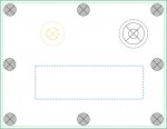
If it helps you, I attached a .jpg that is (supposed to be) a 1:1 scale representation of the locations of the control mounting hole (blue), trim toggle mounting hole (black) and kill switch (orange) relative to each other on that plate in my pictures.
 

Attachments

  • TrimTemplate.jpg
    TrimTemplate.jpg
    83.2 KB · Views: 1
Top