Newbie 12 24 switch on boat wiring issue

spugh2000

Recruit
Joined
Apr 12, 2015
Messages
3
This is my first boat 1990 Lowe v1700. Previous owner unhooked batteries and some wiring and Im tryin to figure things out to keep from taking to shop. On the front panel it has a 12 24 run charge switch, trolling motor plug, and tilt trim. The tilt trim switch works fine but the 12 24 run charge switch was bad so I got a new one. The switch has 6 prongs, three on each side. How do I know what wires go where on the switch?The trolling motor plug on the panel has three wires red orange and black, the trolling motor itself is a 12v 55lb minnkota power drive it has a red and black wire. There are four wires up front coming from batteries in the back red, orange and two black (assuming power supply), there are three batteries in the back, two are deep cycle and one is a starting I was told. There is also a 3 bank onboard charger that is hooked up to 2 of the batteries. Previous owner sent me a pic of how switch was wired up before but was told they werent sure if it was right. I keep getting an error when I try to upload pictures, guess I need help on that too lol. Thanks in advance for any help.
 

alldodge

Moderator
Staff member
Joined
Mar 8, 2009
Messages
40,756
This is my first boat 1990 Lowe v1700. Previous owner unhooked batteries and some wiring and Im tryin to figure things out to keep from taking to shop. On the front panel it has a 12 24 run charge switch, trolling motor plug, and tilt trim. The tilt trim switch works fine but the 12 24 run charge switch was bad so I got a new one. The switch has 6 prongs, three on each side. How do I know what wires go where on the switch?The trolling motor plug on the panel has three wires red orange and black, the trolling motor itself is a 12v 55lb minnkota power drive it has a red and black wire. There are four wires up front coming from batteries in the back red, orange and two black (assuming power supply), there are three batteries in the back, two are deep cycle and one is a starting I was told. There is also a 3 bank onboard charger that is hooked up to 2 of the batteries. Previous owner sent me a pic of how switch was wired up before but was told they werent sure if it was right. I keep getting an error when I try to upload pictures, guess I need help on that too lol. Thanks in advance for any help.

:welcome: to iboats

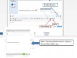
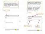
You sure have an issue going on and I'm trying to follow but guess I'm going to need some pics. Here is how you upload pics if there on your computer or a link to another source.
Pic upload 1.jpg

Pic upload 2.jpg

Since you do have a 12V trolling motor I don't see the need for a 12/24 switch unless you already have a 24V charger
 

Silvertip

Supreme Mariner
Joined
Sep 22, 2003
Messages
28,762
Since you have a 12 volt Minnkota, you do not need to put everything back as it was, and without the wiring diagram for the boat it would require input from someone who has the same boat who can take pictures for you. Otherwise it's a guessing game. Here is what I can tell you for sure.

1) You have two deep cycle batteries because they were required for operation of a 24 volt motor (which yours is not). They would also be required if you were to have a motor that ran off of 12 OR 24 volts (also which you do not have).
2) Each of those batteries has a pair of wires going up to the control panel at the bow. This is simply two totally separate 12 volt circuits.
3) The 12/24/RUN/Charge switch was an attempt to make charging the trolling motor batteries simple by plugging the output of a single 12 volt charger into the trolling motor receptacle, thus making it unnecessary to attach it to the batteries. Nice, but an overly complicated system since you have an on-board charger that only needs to be plugged into 120V AC and all three batteries get charged.

Here is my recommendation,
1) To avoid screwing up the resale value of your boat, DO NOT remove any switch or remove any wiring.
2) Install the new switch but leave the wiring as you found it.
3) You have the perfect setup for a 12 volt motor in that you have two 12 volt batteries. That gives you the following options:
a) Wire only one to the trolling motor receptacle so the motor runs from just one battery.
b) Wire both batteries in PARALLEL so voltage remains at 12 volts but you essentially double the run time.
c) Do "b" above but rather than permanently wiring both batteries use a dual battery switch (Perko is just one brand) to select which battery you prefer to run from. This method allows you to use battery #1, battery #2 or both. These switches are available right here on IBoats for about $40 give or take a little.
4) At the trolling motor receptacle, all you need is one 12 volt circuit using any two of the four terminals.
5) Wire the plug on your trolling motor so the red and black in the plug match with the +12 and ground terminals in the receptacle.

Wiring the batteries with a switch is a matter of connecting BAT #1 POS to BAT #1 on the switch. BAT #2 POS goes to BAT #2 on the switch. COM gets wired to the receptacle at the bow. Use one of the wires already in place -- preferably the red one. Connect the NEG terminal on both batteries together and then connect the black wire going to the receptacle to the NEG terminal on either of the batteries (use the black wire already in place). Plug in the motor and go fishing.

To wire the batteries in parallel, simply connect them POS to POS and NEG to NEG. Then use one pair of the four wires going up front as the 12 volt feed to the receptacle. This is not the best approach since batteries permanently in parallel can create issues in that a weaker battery can draw down the stronger battery until they equalize. The Perko Dual Battery switch eliminates that issue.

When this is all done, connect each of the three on-board charger outputs to each of the three batteries. Always charge the batteries after every trip. Don't leave them in a discharged state.
 

spugh2000

Recruit
Joined
Apr 12, 2015
Messages
3
switch%20panel_zpslblliubw.png

Picture of front of panel

trolling%20motor%20plug_zpsfiolgq87.png

Picture of back of panel

12%2024%20switch%20wired_zpseddrjppv.png


Picture of how switch was wired by previous owner

20150412_135700%201_zpsgwnf78ld.jpg

Picture of new switch

20150412_144111_zpstvhtezni.jpg

Picture of power supply

The way the switch was wired up before is confusing me.
 
Top