Advice Wiring Tilt with Two Switches in Parallel

paperklip

Petty Officer 2nd Class
Joined
May 20, 2011
Messages
108
BL Trophy - 1983 Volvo 4cyl AQ125A w/ Penta 270

I'm looking for advice on re-wiring the panel switch back to the Tilt. The previous owner disconnected the main panel tilt switch and installed a stern switch directly. While this is a convenient placement for a tilt switch (trailoring etc), I'd prefer having both switches operational in parallel. Normally this would be easy enough, but I noticed that there are two different types of switches involved.

The tilt has the standard two wires:

IMG_0533_annot.jpg


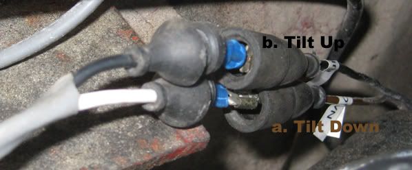
The stern switch is currently wired as follows, directly to the above connections:

IMG_0532_annot.jpg


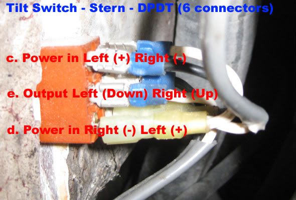
The stern switch appears to be a three position DPDT (momentary-on/hold-on style). As you can see the switch is setup to output +/- or -/+ from the center pair, based on the switch being pressed either up or down.

The panel switch also appears to be a three position momentary-on style, but has only 3 connectors on the back, controlling the + only:

IMG_0535_annot.jpg


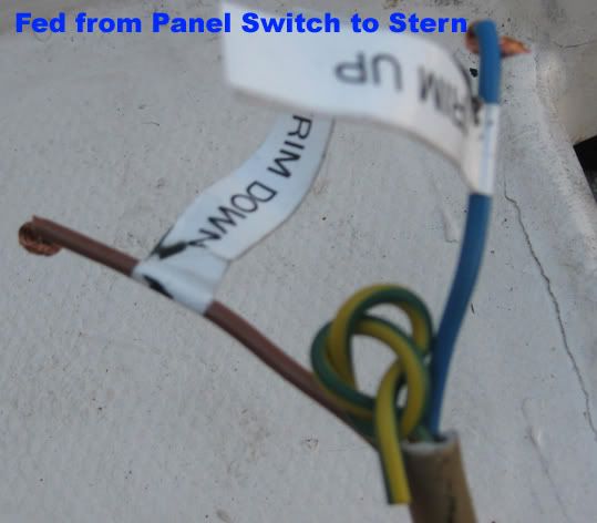
Orange is fed from fusebox, and brown/blue make their way to the stern area (the third yellow/green is not connected anywhere):

IMG_0534_annot.jpg


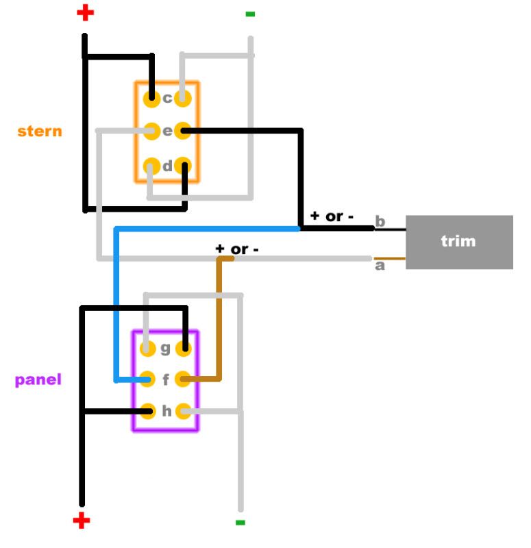
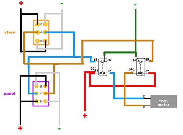
Here's where things stand:

diagram_before.jpg


My problem stems from there not being a negative pole to hook from the panel switch. Obviously just hooking up "g" and "h" to "a" and "b" won't work as there's no "-" when either of those is hot (+).

Any help is greatly appreciated! Thanks.
 

Fed

Commander
Joined
Apr 1, 2010
Messages
2,457
Re: Advice Wiring Tilt with Two Switches in Parallel

Well that's weird, I don't see how that could have ever been connected to work.
Let me say I have zero experience with Vovos.

First I'd try & track down a wiring diagram to see how it was originally supposed to be wired before the PO got into it.

Could there be any relays hidden away, perhaps the panel switch was switching relays and the stern switch was switching directly to the motor?
 

paperklip

Petty Officer 2nd Class
Joined
May 20, 2011
Messages
108
Re: Advice Wiring Tilt with Two Switches in Parallel

I looked around and didn't find any relays in/around the panel box or the stern area. I went ahead and bought a new panel switch with 6 connectors (same as the stern) and hooked it up as follows:

diagram_after.jpg


I checked all voltages before hooking up to the trim and all seemed well with 12.6V showing as expected for either switch (panel and stern). However, when I connect everything (as above) and try it, the panel switch "up" does not work (down is fine).

With the unit all the way down, "up" starts the motor (for the slack) but as soon as it has the unit weight on it, it stops. So it seems to be just because of the load. With the meter hooked up I see the voltage dropping to around 4V. The stern switch does raise the unit, but VERY slowly.

I'm thinking there are some missing components here (relays?). Anyone know where I can get an original wiring diagram for this one?
 

Fed

Commander
Joined
Apr 1, 2010
Messages
2,457
Re: Advice Wiring Tilt with Two Switches in Parallel

I'm thinking there are some missing components here (relays?). Anyone know where I can get an original wiring diagram for this one?
I think you're on the right track now T&T motors draw fairly high current and using relays down at the back of the boat will reduce the voltage drop considerably.
The wiring/relays needs to be interlocked so that activating both switches at the same time but in opposite directions doesn't create a dead short so be careful until you get it sorted.
The way it's wired now you're in dangerous territory.
Check in the Volvo I/O Forum surely someone in there owns a Volvo.
 

paperklip

Petty Officer 2nd Class
Joined
May 20, 2011
Messages
108
Re: Advice Wiring Tilt with Two Switches in Parallel

Ok, I bought two relays for the 270 lower unit (Volvo Part# 876037), and referred to this diagram from Don (on another thread, also for the 270):

attachment.php


I then wired it up (somewhat hastily) as follows:

diagram_wRelays.jpg


But when I tested it, both relays got fried. :-( Ok, so now I need to get two more relays (fine) but can someone show me where I messed up the wiring?

In my scenario, there are a few important differences from the wiring diagram.
(1) My tilt motor only has two wires (#4).
(2) I don't have a "warning lamp" (#8).
(3) I don't have a wired setup for the retaining pawl/thrust bar (#5).
(4) I don't have a "motor cut-out" (#6).
 

paperklip

Petty Officer 2nd Class
Joined
May 20, 2011
Messages
108
Re: Advice Wiring Tilt with Two Switches in Parallel

It looks like my image was getting cutoff so here's a smaller version.

diagram_wRelays-1.jpg


Any help is appreciated!
 

Fed

Commander
Joined
Apr 1, 2010
Messages
2,457
Re: Advice Wiring Tilt with Two Switches in Parallel

Although not ideal I don't see why your relays fried with the way you had it wired.
Did you download a manual for it yet?
I have the manual on my desktop so let me know if you need it, I'll keep it for a few days.
I would bring the whole system back to stock standard and get it working as it was designed then worry about wiring in the extra switch if you still think it's worth it.
Starting to make alterations on an already half hacked system is just asking for trouble.
 

paperklip

Petty Officer 2nd Class
Joined
May 20, 2011
Messages
108
Re: Advice Wiring Tilt with Two Switches in Parallel

Thanks. Can you attach the manual here for me please?
 

Countryboy73

Recruit
Joined
Jun 18, 2011
Messages
1
Re: Advice Wiring Tilt with Two Switches in Parallel

Here you go.

Could I possibly get that manual link sent to me as well, I've been working on trying to get the wiring straightened out for two days now and have blown 2 fuses so far trying to get it to work properly... If so, it would be greatly appreciated and helpful...
 
Top