Fuel gauge won’t go below 1/2 full

alldodge

Moderator
Staff member
Joined
Mar 8, 2009
Messages
40,756
new sender is out of tank do arm length does not come in to play as I am moving up and down from full to empty by hand to see movement on gauge

I understand what your saying (the fuel gauge goes full to empty as your move the arm) but appears your not understanding my point.

Assume you tank is in the center of the boat. (I do not know how long the float arm is)

Being in the center, most tanks are not square or rectangular. They are more of a trapezoid. Deeper in the rear then the front, and also more shallow on the sides, and can have baffles.

So if the arm is longer and comes in contact with a baffle, it won't go all the way down.

If the arm should be front to front to rear and its is placed sideways, then it may not go deep enough.

Think of a triangle and picture the arm going sideways in the tank, the arm won't reach the bottom. Just one example. Same goes as if there is a baffle in the way

float.jpg
 

Dannich

Seaman Apprentice
Joined
Jul 7, 2019
Messages
32
Sender is not in the tank. So the tank currently has no impact on the level seen on the gauge.
i am moving the arm from full position to empty by hand. When in full position it shows full on the gauge. When in empty position it shows 1/2 tank on the gauge.
 

alldodge

Moderator
Staff member
Joined
Mar 8, 2009
Messages
40,756
Sender is not in the tank. So the tank currently has no impact on the level seen on the gauge.
i am moving the arm from full position to empty by hand. When in full position it shows full on the gauge. When in empty position it shows 1/2 tank on the gauge.

Told ya I was old but do understand, thanks.
 

Dannich

Seaman Apprentice
Joined
Jul 7, 2019
Messages
32
Ok so I have made some progress.
the gauge and sending unit work perfectly. There is a problem at my selector switch fir left and tight tank.
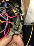
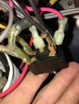
see attached photos.
there is a diode going from each sending unit wire to ground on a right, center, left switch.
the grounds are joined on the bottom of switch and then the leads for the sender are switched.
with the diodes wired in I get the no less than 1/2 full reading when sender is at the empty position.
when I take the diodes off the gauge reads perfectly with the movement of the float arm.
what are the diodes for because they are messing things all up.
 

Attachments

  • photo321488.jpg
    photo321488.jpg
    1.9 MB · Views: 0
  • photo321489.jpg
    photo321489.jpg
    1.9 MB · Views: 0

Dannich

Seaman Apprentice
Joined
Jul 7, 2019
Messages
32
Looks like this stumped everyone .
I bought new diodes with no success
do I even need them ??
 

alldodge

Moderator
Staff member
Joined
Mar 8, 2009
Messages
40,756
No need for the diodes, they help dissipate voltage spikes, and I don't see this being an issue

Is the switch for 1 gauge and 2 senders (port/starboard)?
 

Dannich

Seaman Apprentice
Joined
Jul 7, 2019
Messages
32
Correct
1 gauge for 2 senders.
im fine not running the diodes as it works perfectly.
just want to insure it’s safe. Nothing blows up in particular
 

alldodge

Moderator
Staff member
Joined
Mar 8, 2009
Messages
40,756
Don't see anything blowing up, but would like to know how the switch works.

Normally there would be two connections in the middle, and that would make it a DPDT

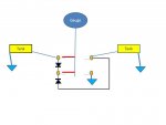
Not finding two connections in the middle would make me think it would be a single "common" pole, so SPDT. My first drawing shows how it might work. The Red leads would be moved when the switch is moved from one side to the other.

Slide1.JPG

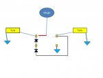
Now if the poles are just dumb and make no connection inside, then this would be how it is

Slide2.JPG

Now if you can, remove all the wires/diodes and use a ohm meter to see how the connections are made
 

Dannich

Seaman Apprentice
Joined
Jul 7, 2019
Messages
32
There are 3 terminal at top of switch. The middle goes to the gauge the left goes to left tank and the right hoes to right tank.
there are 2 terminal at bottom of switch these are bridged to each other and are for ground on one side and the diodes goes to the other side. Then on the right and left top terminal there is the sender leads from the tanks and a diode that goes to the bottom left side of the ground.
 

alldodge

Moderator
Staff member
Joined
Mar 8, 2009
Messages
40,756
See photos from earlier post

My drawings were made up from looking at the pics.
My question is what connections are made "inside" the switch when it is flip from one position to the other?
 

Dannich

Seaman Apprentice
Joined
Jul 7, 2019
Messages
32
When switched it connects the top left to muffle or top right to middle the middle goes to the gauge and the right left are the sender wires for each side
 

alldodge

Moderator
Staff member
Joined
Mar 8, 2009
Messages
40,756
ok, are there any connections made from the middle to the lower diode connection or ground ?

If not, then the post is just used to hold and that would be a bit weird.
 
Top