Use the battery's neg post as your main "mother earth" reference......i.e., connect the volt meter's negative lead to the batt's neg post (the lead-Pb part) and leave it there. Now using the meters positive lead probe things.....
As you probe things with the positive lead of the meter, ALL grounds (usually blk wire) even the unmarked (neg) post of the cap, if wired properly, should NOT read anything higher than 0'ish volts......If so, you have flaky ground somewhere allowing its ground to "float" up above the battery's 0V terminal voltage .......hence "8V".
Same goes with the positive stuff, with the meter's neg lead STILL attached at the "mother earth ground referance point".........Any 12VDC feeds have to be 12V'ish, else you have a flaky connection in the 12V feed lines allowing the 12V to "sag" below the battery's terminal voltage of 12V'ish


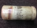
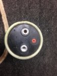
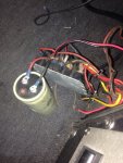
 I just purchased a 1988 Cajun 19' bass boat and have discovered a serious electrical issue that has me off the water until I can get it resolved. In the process of troubleshooting the issue (low voltage to the live well pumps and bilge pumps) I have come across what looks like a capacitor that is wired into the power distribution block (see attached photo). Does anyone recognize this set up and what is the function? Background - When I measure voltage going into the block, it checks 12.6V. The positive connection that attaches to the cap(?) also measures 12.6V. However, when I connect my voltmeter to the "other" unmarked lug on the "cap", I measure around 8V...that value never changes, even when I remove the "cap" from the circuit. When I check the voltage on the "cap" removed from the circuit, it measures 0.3V negative, when the meter is connected + to + and neg to the other lug. Any ideas? Thanks. Bannister


