ICOM OPC-980 clone cable adapter

Status
Not open for further replies.

sven98de

Cadet
Joined
Jan 15, 2016
Messages
6
Hi,
I'm looking for an ICOM OPC-980 pinout or schematic.
Any ideas ?

Sven
 

Attachments

  • OPC980.jpg
    OPC980.jpg
    14.5 KB · Views: 1

StingrayMike

Petty Officer 1st Class
Joined
Aug 17, 2014
Messages
355
It is just a cable. The cable actually only uses 2 pins on the command mic plug. Cant remember which ones though,
I have the pin out at work, I will get it to you on Monday if you still need it.
the software does everything you need. What you plan on doin?
 
Last edited:

sven98de

Cadet
Joined
Jan 15, 2016
Messages
6
Hi,
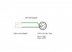
it would be very kind of you to send me the OP-980 pinout. I haven't got one till now.
This season I will change my sailing area from Germany ( Baltic sea ) to the Netherlands.
The dutch use channel 31 to contact the harbour master, in Germany channel 31 is not common and
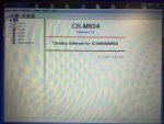
so it's not possible to choose it at the marine transceiver. I plan to add channel 31 with the cloning software.
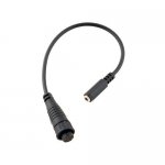
Do you perhaps know what kind of 8-pin connectors ICOM use for their microphones, are they proprietary or are
there any other sources, besides ICOM, available ?

thanks in advance
Sven
 

StingrayMike

Petty Officer 1st Class
Joined
Aug 17, 2014
Messages
355
There are different types of cable adapters for all styles of radios. What type of radio do you have?
The 8-pin cables are only for ICOM, but you can get the cable anywheres. If you dont have a cable already, get a command mic extension cable and cut it inhalf.
I used that half and soldered the USB portion of the kit to it using 2 pins.
The cloning software can be difficult to get since iit is only supposed to be owned/used by ICOM dealers. Do you aready have the software?
BTW-the cloning software that comes with the kit is just the drivers, not the actual cloning software.
 

sven98de

Cadet
Joined
Jan 15, 2016
Messages
6
I have an ICOM IC-M602 and the 8-pin extension cable as well. I think I'll do it like you do and cut it inhalf. I've downloaded the IC-M602 service manual and there the microphone connector is named : LTW-8MP-C. The manufacturer is " Technical Electron Co. LTD"
This is the connector at their website: http://www.technical-e.co.jp/eng/material/csv_pdf/LTW8MPC.pdf
But unfortunately there's no distribution list at their site.
The software I have shows in the "About" window "CS-M602 Revision 1.0, (C) 2002 ICOM Inc."
 

StingrayMike

Petty Officer 1st Class
Joined
Aug 17, 2014
Messages
355
I will have to check to see what my software at work says.
I know i ordered the cloning kit and it came with cables and drivers only, then had to get the cloning software seperate from ICOM, since we area dealer, it was simple.
If you open the program, what comes up? should be something related to the radio.
 

sven98de

Cadet
Joined
Jan 15, 2016
Messages
6
If I start the program the opening screen is:

CS-M602
Revision 1.0
Cloning Software for IC-M602
( C ) 2002 Icom Inc.
 

StingrayMike

Petty Officer 1st Class
Joined
Aug 17, 2014
Messages
355
Seems right. This is a pic of the program that I use.
for the actual cable, I cut off the 3.5mm jack on the adapter and solder the lead that was to the center to pin 8 on the cmd mic plug(green) and the lead that was going to the sleeve(bottom) to pin 4 (blue) on the cmd mic plug.
the tip of the 3.5mm jack is not used.
IMG_1316.JPG
 

Attachments

  • IMG_1316.JPG
    IMG_1316.JPG
    34.6 KB · Views: 1

sven98de

Cadet
Joined
Jan 15, 2016
Messages
6
No Title

My program has a similar entry screen but CS-M604 is replaced by CS-M602.
I've made a sketch from the adapter, is it correct ?
I figured out that the cmd. mic connector is an Amphenol LTW Standard B, model : LTW BD-08BFFA-LL7001
Thank's for your efforts.
 

Attachments

  • photo236809.png
    photo236809.png
    65 KB · Views: 8
Last edited:

StingrayMike

Petty Officer 1st Class
Joined
Aug 17, 2014
Messages
355
I went back and looked at my wiring schematic and this is what I did. The colors were not green and blue.
on the 3.5mm jack, the leads were gray and black ( I couldn't read my own writing).
so the gray would go to pin 8 and the black would go to pin 4.
 

Tws24554

Recruit
Joined
Apr 30, 2019
Messages
2
I went back and looked at my wiring schematic and this is what I did. The colors were not green and blue.
on the 3.5mm jack, the leads were gray and black ( I couldn't read my own writing).
so the gray would go to pin 8 and the black would go to pin 4.


Twice - This is also not permitted and also off topic. And the thread is old and inactive to boot. Please read and follow our rules.
 
Last edited by a moderator:
Status
Not open for further replies.
Top