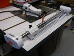
Minn Kota 599 Project

Status
Not open for further replies.

gm280

Supreme Mariner
Joined
Jun 26, 2011
Messages
14,605
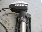
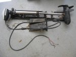
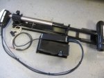
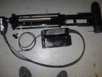
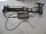
I myself have been looking for info on an old Minn Kota 599 12/24 volt trolling motor. And in my search I've seen a lot of folks ask the same questions. And that question is; "Does anybody have a schematic diagram for the Minn Kota 599 Trolling motor"? Well I not only have such a schematic (self drawn), but I actually bought an old one that was, for all practical purposes, totally worn out. SOOooo, I decided to refurbish this old trolling motor and that is exactly what I've done. Yes the Minn Kota 599 is a 12/24 volt (switchable) 41lbs thrust trolling motor with 8 speeds. However, they get those 8 speed from 4 speed at 12 volts and the other four speeds at 24 volts. It has a monstrous motor and is quite heavy as well. So here is what I started with when I purchased this thing. :facepalm:
IMG_0015.JPG
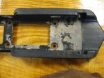
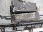
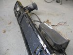
Yes I know, why would anybody buy such a piece of junk in that condition... :eek:
IMG_0016.JPG
IMG_0018.JPG
IMG_0016 (2).JPG
IMG_0017.JPG
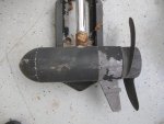
Yes the lower bearing assembly is toast as well...but so was the upper bearing assembly too...
IMG_0018 (2).JPG
IMG_0027.JPG
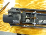
Not much to look at is it. Not pretty at all...

Virtually nothing on this trolling motor was in proper working order. But it did run...sorta...

And so this refurbishing project is on.
I bought it off Craigslist, of course, and I think I gave $50 dollars for it. And looking at it, it doesn't even look worth $50 dollars...yet!
 

gm280

Supreme Mariner
Joined
Jun 26, 2011
Messages
14,605
Now I start disassembling it. but before I get ahead of myself, out comes the camera. I've taken well over 50 or more pictures ( I mean they are digital anyways) of this thing from start to finish and amazing how many times I have gone back to the pictures for both reassembly (coming later on) and even the wiring at the different switches. So here are the disassembly shots;
IMG_0015 (2).JPG
Removing the actual trolling motor from the holding bracket was easy...
IMG_0022 (2).JPG
I started taking picture immediately. And yes everything is either rusted, or corroded aluminum... Nothing was spared.
IMG_0022.JPG
Have to get wiring pictures.
IMG_0024 (2).JPG
You can see the bubbled up paint from the aluminum corrosion underneath.
IMG_0024.JPG
And the old nomenclature plate...gone for sure...
IMG_0025 (2).JPG
Top of the head cover off and look see inside...
IMG_0029 (2).JPG
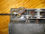
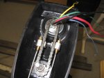
A picture of the COMMAND POST Momentary/Off/Continuous rocket switch wires...
IMG_0031 (2).JPG
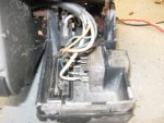
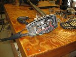
A look under the foot pedal...
IMG_0031.JPG
And of course the speed selection rotary foot switch wiring.

I have tons more pictures if anybody wants or needs to see a certain section of the build beyond what I am posting...
 

gm280

Supreme Mariner
Joined
Jun 26, 2011
Messages
14,605
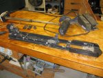
Now comes the interesting section of the disassembly. The actual control cables that move the trolling motor. This is very interesting to see and reconfigure after the refinishing work was done. I've used these pictures a lot in the reassembly...
IMG_0032 (2).JPG
This has got to be an engineering feat in itself. To make this work, somebody had too much time on their hands... :noidea:
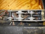
There are two cables. Each one originates from this section and has its own cable wrapper/sheild (for lack of the actual word) from this section to the trolling motor head unit. And the movement of these cables steers the motor.
IMG_0026 (2).JPG
You can see on the left hand section the two cables entering the head unit and attached to the drive chain for steering. Clever setup...
IMG_0027 (2).JPG
I little different shot. You can see those two cables better. And notice the rust on the chain as well.
IMG_0033 (2).JPG
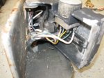
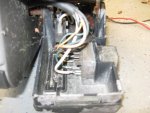
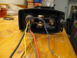
You can see the cover is off the COMMAND POST section where both the power comes in and those steering cables are setup.
IMG_0035.JPG
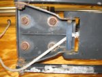
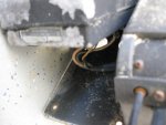
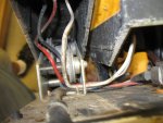
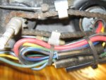
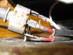
Here is a picture of the 12/24 volt selector switch and the metal tab it mounts to under the foot steering control section. Notice the two red wires and one white wire. The main power cord has one red, one white and one black. So the red is for the 12 volt side and the white for the 24 volt side. The center red goes to the other switches as you will see later on.
IMG_0037.JPG
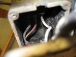
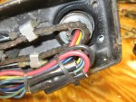
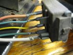
And let's not forget about the rotary speed selector switch wiring. All these wires actual connect to the motor via the head unit. So this motor is wired for the four speeds and depending on either 12 volts or 24 volts selected, you get the eight speed options.
IMG_0038.JPG
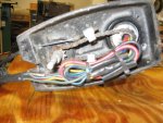
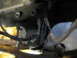
There is a continuous and momentary selectable rocket switch located on the COMMAND POST and this foot push to run switch is wired for the momentary option. I realize this looks really confusing, but I will clear it all up later on. These are just the pictures I took for the basic wiring of all the switches.
IMG_0033.JPG
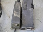
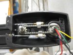
I talked about the COMMAN POST. Well this IS the COMMAND POST on the left hand section of the foot control unit. It actually says COMMAND POST, but the white lettering is gone. You can also see the mom/off/cont selecting rocker switch on the end and the power cord going in...
 

gm280

Supreme Mariner
Joined
Jun 26, 2011
Messages
14,605
And a few more shots of the unfinished unit;
IMG_0028 (2).JPG
Here is a little further away shot showing both the wiring and the steering setup in the head unit.
IMG_0028.JPG
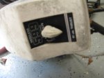
This is a shot of the head unit with the cover on and the indicator pointer. Not really clear, but the verbiage tells that it is a 599 model, weedless, 12/24 volt and 41 pound thrust...
IMG_0031.JPG
Here is that rotary speed selector switch before disassembly. All these shots actually do come in handed when reassembling again because you want to get the switches in the same position as original so nothing interferes with its operation.
Minnkota (20).JPG
Here is a shot of the wires that are in the head unit that go to the motor. I've tested each one to verify the lower motor unit was good. And each different color has its own speed... Black, of course, was the ground and all the other colors works from that ground. And so you can see that there are four colors for four speeds.

Next comes the refurbished pictures, the rebuilding pictures and wiring info.
 

gm280

Supreme Mariner
Joined
Jun 26, 2011
Messages
14,605
I did repair even the drive/steering cables because they too were toast. So I removed the actual inside cable and decided that standard picture frame wire sold at Lowes was the exact same cable. And it was. So I bought about 12 feet and this is how I repaired the drive/steering cables.
Minn Kota (1).JPG
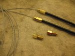
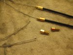
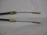
If you look real close at the factory drive cables they are merely brass fittings threaded onto the outer cable shield. I found this out when I thought they were going to be trash. I thought I would play with them and see how they were assembled. And I was able to thread off the brass ends. SO, I thought the outer sheath is still good, why don't I buy new internal wire and rework them. And that is what I ended up doing. As you can see I threaded the new cable through the sheathing and threaded on the brass fittings again. Really easy. Minn Kota (2).JPG
You can see the cable ends and the other brass ends for the other end of the sheathing.
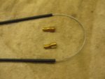
Minn Kota (3).JPG
Now all I have to do is cut the cable and thread the brass ends on this side...
Minn Kota (4).JPG
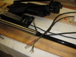
I also checked and clean all the wires and terminal ends to make sure they had good connections. In the background you can see the mounting assembly sitting after refinished.
Minn Kota (6).JPG
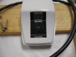
And here are the new plates I made for the top of the head cover. Yes even the finger print smudges are visible too...It will clean up nice and clean though. We, wife and I, have a really large LASER engraver and can make all types of plates for things like this. The old plates were really ratty looking...

Until next time, you all have a great day... :thumb:
 
Last edited:

S.A. Baker

Petty Officer 1st Class
Joined
Aug 9, 2015
Messages
227
The amazing thing is your top cover was still white! Both of my old 555's the top covers are now yellow! One of mine is a bow mount ,and the other is a transom mount. I totally rebuilt the bow mount , but my rotary switch is DOA! It has a toggle switch for high/low, and the foot momentary switch still works...so that is what I have to use to run it. Would be nice if the rotary switch worked. Someone soldered the spade connectors to the terminals...and it does nothing. Can't even get it apart! Both of mine are from the seventies and still going strong? Yours is looking very good so far!
 

gm280

Supreme Mariner
Joined
Jun 26, 2011
Messages
14,605
The amazing thing is your top cover was still white! Both of my old 555's the top covers are now yellow! One of mine is a bow mount ,and the other is a transom mount. I totally rebuilt the bow mount , but my rotary switch is DOA! It has a toggle switch for high/low, and the foot momentary switch still works...so that is what I have to use to run it. Would be nice if the rotary switch worked. Someone soldered the spade connectors to the terminals...and it does nothing. Can't even get it apart! Both of mine are from the seventies and still going strong? Yours is looking very good so far!

S.A. Baker, the reason the top cover is white is because I painted it back white. And then a clear coat on top of that. And those colors are PPG Shop Line auto type paints. On your rotary switch, if you work really carefully, you may be able to disassemble the rotary switch and clean the internal contacts. May be worth a try... :noidea:
 

gm280

Supreme Mariner
Joined
Jun 26, 2011
Messages
14,605
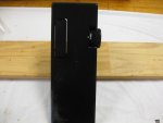
Here are some of the parts after cleanup and painting them ready for assembly again.
Minnkota (1).JPG
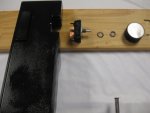
Here is the foot pedal and the rotary switch with hardware ready to go together.
Minnkota (2).JPG
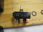
And the actual switch with the part number. However, I did try to locate a new one just to see if they were still available, and nothing... But if I actually had to find one, I think I could...
Minnkota (3).JPG
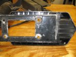
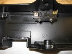
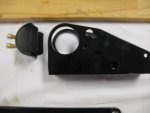
Here is the underside of the foot pedal with the momentary push switch mounted already.
Minnkota (4).JPG
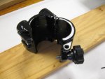
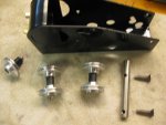
Here are the parts laid out for the mounting assembly.
Minnkota (5).JPG
The foot pedal with the rotary switch in place.
Minnkota (6).JPG
The trolling motor shaft clamp assembly with the know assembled..
Minnkota (7).JPG
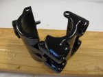
Another angle where you can see the four mounting areas where the springs go..
Minnkota (8).JPG
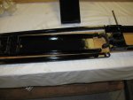
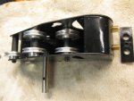
You can normally see this part because it is actually hidden under the COMMAND POST cover. But this is where the actual steering cables get mounted.
You can see the two brass fitting that thread on the steering cable ends.
Minnkota (10).JPG
And here are some of the parts that go into the assembly for the steering cables. The long rod on the original was so rusted and pitted, that I turned a stainless steel one out and drilled and threaded it to the original specs... Easy Peases...
Minnkota (11).JPG
And those parts assembled with the rod in place as well.
Minnkota (14).JPG
And the sub-assembly with the cable ends installed. Without those two little stops, there would be no way to secure the cables.

More to come.... :thumb:
 

S.A. Baker

Petty Officer 1st Class
Joined
Aug 9, 2015
Messages
227
gm280....your top cover even looks white in the first pic before work. I may try to fix the rotary switch on mine if I can get it off! Don 't know why the connectors ate soldered on though. Have plenty of down time....fall is upon us up here and the fishing just completely turned off! I was expecting it to pick up before the water got stiff! Your motor is really looking good. I kinda prefer the older stuff myself.
 

gm280

Supreme Mariner
Joined
Jun 26, 2011
Messages
14,605
gm280....your top cover even looks white in the first pic before work. I may try to fix the rotary switch on mine if I can get it off! Don 't know why the connectors ate soldered on though. Have plenty of down time....fall is upon us up here and the fishing just completely turned off! I was expecting it to pick up before the water got stiff! Your motor is really looking good. I kinda prefer the older stuff myself.

S.A. Baker, I have taken lots of all types of switches apart before and taken out the brass/copper components out and clean them up removing any burnt area if there were any and then a little grease to the needed sections and reassembled them again. And they work like new. That is unless the insides are totally burnt away. But all switches are merely brass/copper components that click together to make contacts much like old ignition points work and not much more. So they can be refurbished when you can't find a new one... If you really want to remove the solder, you can take some solder wick (it is a desoldering wire/wick available in most electronic part stores) and apply some heat from a soldering iron tip and the solder will wick off the area into the wick. A little trick using solder wick, apply a little bit of solder to the wick as you heat it up, to help transfer the heat and the wick will suck the solder from the area you are wanting to clean up. And I have successfully removed solder from a lots of parts in the past. And if you know how to use solder wick well, you can almost remove every bit of solder. I have near about clean contacts back to copper metal again using solder wick. So there are ways to refurbish lots of part if you go slow and know what you are doing. But you will never learn without trying either. And thanks for the kind words about the trolling motor. This isn't my first trolling motor refurbish. But it is that most involved thus far... I like doing such things. :thumb:
 

gm280

Supreme Mariner
Joined
Jun 26, 2011
Messages
14,605
Okay for a little more update and info. I have assembled almost everything now. And as usual, there is a sequence to such assembly. And of course I didn't realize such a sequence on the first try. So I assembled things and then disassembled then again so I could do it in the "special" order so everything works out correctly. I can say that the cables and pulleys are interesting and I've learned a lot assembling them and disassembling them again. Here are some more pictures;
Minn Kota (12).JPG
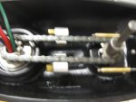
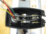
The steering heart of this trolling motor are these cables. And they thread into the head unit so you can control the direction from the foot section. But the are soldered onto the brass threaded section to allow for alignment and take up any slack. So the original threaded parts were toast. So I took two long brass screws and cut the heads off and drill a hole through the centers. Then pushed the cables through and soldered then in place. These will actually be removed as I assembly the steering setup as you will see later.
Minn Kota (7).JPG
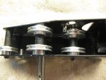
Yes I know this is really blurry, but I wanted to show how and where those cables at attached in the head unit. nothing more...
Minn Kota (8).JPG
This is blurry as well but shows the usual setup from the steering. Those threaded brass parts will eventually thread into the two aluminum parts attached to the chain.
Minn Kota (10).JPG
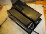
Here is the assembled foot section with the wiring setup. You can see the COMMAN POST label and the switch assembly that allows the operator to turn it off, or select continuous running or momentary using the foot press switch. The finish came out nicely.
Minn Kota (9).JPG
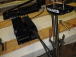
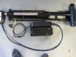
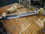
And here is the foot section and the head unit attached to the shaft and motor. Looks totally different then what I started out with. And in the background is the mounting assembly... I finished up wiring everything except the wires to the actual motor in the head. But those are simply match the color connections.

Hope to finish this tomorrow...
 

gm280

Supreme Mariner
Joined
Jun 26, 2011
Messages
14,605
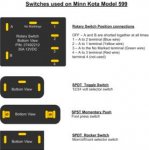
I guess I should post the schematic and switch layouts. Here are those two diagrams:

Minn Kota 599 Switchs.gif

These are all the switches that the Minn Kota 599 trolling motor uses. I shown all of them from the back view for better clarity.

Minn Kota 599 Schematic.gif

And the schematic diagram from the actual Minn Kota 599 trolling motor itself. It is four speed but the interesting part is the Rotary switch wiring. Why they didn't use the five possible positions. who knows. The three wires coming from the input batteries are Red, Black, and White. The white is the 24 volt positive input and the red the 12 volt positive input with the black the usual ground. The first SPDT switch is located under the foot pedal at the read of the assembly and is labeled 12/24 volt with the toggle switch selectable options. The second SPDT switch is located in the COMMAND POST section and is a center off rocker type switch. It allows selection of continuous run or the usual momentary press switch on the foot pedal. The SPST press switch is located on the foot pedal and is the usual press to run type. And the Rotary switch is also located on the foot pedal with the selectable four speed as marked and the off position as well. It has an unused fifth position that is not marked or used between the fourth speed and the off position... Other then this, there is not much more for this trolling motor. I will probably post the finished results and that will be the finish of this project... I hope this helps some folks because I know there are still these 599 models being used and folks are looking for the schematic and other things about it. :thumb:
 

S.A. Baker

Petty Officer 1st Class
Joined
Aug 9, 2015
Messages
227
I wonder if any of that wiring is similar to mine....other than the 12/24 part. My rotary wiring is very suspect! I've had about every switch on this boat apart to repair and clean! That's what's nice about the old stuff. It's repairable,,,not all throw away Chinese parts!
 

gm280

Supreme Mariner
Joined
Jun 26, 2011
Messages
14,605
I wonder if any of that wiring is similar to mine....other than the 12/24 part. My rotary wiring is very suspect! I've had about every switch on this boat apart to repair and clean! That's what's nice about the old stuff. It's repairable,,,not all throw away Chinese parts!

S.A. Baker, after I looked at the break down view of your 555 model, it looks like the two are basically the same with the exception of the 12/24 volt switch option. I would really look at your speed selector switch again and see if you can figure out a way to take it apart. Go slow and easy and you may be able to disassemble it and clean the contacts inside and make everything work again. I have taken rocker switches, toggle switches and even rotary type switches apart, and for the most part, a simple cleaning and they work again like they are supposed to. If you find one with really bad burnt contacts, well that is a total lose. But otherwise, the normal light burnt spots are easy to remove and clean. And if you need a break down for you 555 model trolling motor, here is one. It also covers the 599 but lacks the 12/24 selector switch and wiring... That's the only difference I can see...


Seems like a lot of parts, and I guess it really is, but not that difficult to refurbish as well. Hope this helps you out some...
 

gm280

Supreme Mariner
Joined
Jun 26, 2011
Messages
14,605
And this brings this project to a conclusion. It is all assembled again and you can see what it looks like. I posted this project for two reasons. I, after looking for a typical schematic diagram for this Minn Kota 599 12/24 volt trolling motor and finding ZERO, zip, nada, nothing, and seeing how many others were searching for the same thing, I decided to make this project to help others rebuilding theirs. And I drew up the schematic and even the switch connections. And secondly, I want to show others that even a really bad looking trolling motor for very little money can be refurbished to a very nice looking and running trolling motor again. It just takes some time and a little effort. If you are the type that enjoys refurbishing things, this is an easy to do project. If you are not that type person, then forget this project and buy new... So here are the final pictures; Minn Kota (17).JPG

Here are how the cables are attached to the chain. I soldered them to the brass threaded parts and that give a large range of adjustments if you need to adjust anything. In this shot, I have yet to make the final wire connections. But they are merely match the colored wires to each other and zip-tie them out of the way like they were initially. Minn Kota (18).JPG

A little blurred, but another angle to show the cables setup. Minn Kota (14).JPG

And here is the final assembled trolling motor. Doesn't look too bad now.
IMG_0015.JPG
Remember, this is what I started out with and... Minn Kota (16).JPG

This is what I finished with... Totally usable and not bad looking either. So don't let some older things pass you by because they can, for the most part, be rebuilt and useable again... Minn Kota (13).JPG

And you can do this too. Thanks for looking...

And you all have a wonderful day... :thumb:
 
Last edited:

S.A. Baker

Petty Officer 1st Class
Joined
Aug 9, 2015
Messages
227
Great project gm280 ! Your wiring schematics alone are sure to benifit my project! I have them saved! Nice work!
 

gm280

Supreme Mariner
Joined
Jun 26, 2011
Messages
14,605
Thanks S.A. Baker, I honestly appreciate your response. And I really think the same wiring schematic will work for your Minn Kota 555 model as well. Like I said, the only difference I see is the 12/24 volt option switch on the 599 model. So it should work perfectly. I have rebuild other trolling motors as well. I have a very nice Motorguide III I recently built too. It is really nice. Surprisingly they still have some parts available for those older trolling motors. And the bearings are so universal that they are available and really cheap. That is what usually give out on those TMs.
IMG_1.JPG
Started with this...
Motor Guide III-Sized.jpg
Ended with this. Basically the same procedures...like new!
 

NYBo

Admiral
Joined
Oct 23, 2008
Messages
7,107
I know this thread has been dormant for a week, but all I can say is
:hail:
 

gm280

Supreme Mariner
Joined
Jun 26, 2011
Messages
14,605
I know this thread has been dormant for a week, but all I can say is
:hail:

Ha NYBo, thanks! I was just trying to present a rebuild trolling motor project to show they too can be refurbished and used again. You can buy those older trolling motors really cheap off places like Craigslist and EBay and then with a little TLC, and some new parts easily obtained, you can have a perfectly working TM again... Hope this helps others too... Thanks again!
 

LadyBusiness

Recruit
Joined
Apr 18, 2016
Messages
1
I'm so happy I stumbled upon your thread as I've just inherited the very same trolling motor from my parents!! According to them "it works.....kinda". Ha! I was wondering what you used to clean all the parts...certain chemicals, tools? Also the type of paint? Did you reuse all the original components (except for the cables)?? Thanks!!
 
Status
Not open for further replies.
Top