One peek inside tells the whole story.......:facepalm:
Meter I'm using is this one. Cheapie for sure, but apparently has a diode test.
The other side (the white banded side/cathode) should be around 12V = ("12.46V" - 0.5'ish V = 12V) if the diode is good AND is forward conducting current...........(which it should be doing in our current setup and is perhaps why the flex voltages are not there)
All of the other functions are something I need to learn.
Using the diode check I get 637
If I reversed the leads I get 1 (continuity?)
but if I put the negative probe on to positive battery, with positive probe On diode I get -12.5 V on one side, and -12.17 V on the other side
I think also a little perspective on future meter usage and to perhaps alleviate any confusion when you reverse a meter's +/- leads during a voltage reading is warranted here.......
For example, if you measure "-12.5V" but when you "reverse the leads on the same to points you see "0v"
This, if you think about it, is impossible! If you measure the same two exact points, right?
It has to be either +12.5V in one direction or -12.5V in the other, right?
Perhaps think about it in terms of measuring directly across a battery's +/- posts. In one direction with the leads, the meter reads +12V and the other, the meter reads -12V. The potential difference (the voltage your measuring) has to still be there, you've just changed how your meter referenced the polarity with the reversal of the meter leads.
I was on the D1 diode. 100% sure on that.
With neg meter probe on neg battery terminal, and positive probe on diode, I got no reading at all.
So, I swapped those around. Of course now the bottom of the board shows 12V when probed with + probe and - probe on battery ground (like it's supposed to, right?)


k
But wait........Post #71
You had +12V once. Back up and start again..
Two wire set up again, negative meter lead to negative battery post, probe the foil again where you KNOW you measured +12V previous. A sanity check if you will...........It's (+12V) there still right?
Now move JUST the positive meter probe to the diode (D1).........measure both sides plz.
(Plz don't swap meter leads and wires around anymore, it's confusing you/the readings. Leave the negative probe on the battery negative post until further notice)
The foil area you just checked again here and back in post #71, told me you had +12V, is the SAME electrical point as the anode (non-banded) side of D1.
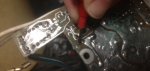
See the schematic post #69 and the pic's below.........A "via" is a printed circuit board's electrical method of connecting top layer traces (foils) to bottom layer traces (foils).
It has to be +12V still...........no magic.
Or...........
gm.........you were nice to the via's weren't you? It looks like when you removed the old relay's, you had to de-solder a relay lead from that via...............Is this a smoking gun?
jeep.......focus!!, We needs some stable readings, lol, I smell victory.
Okay I hope that last picture you shown is of another board and not the one I repaired. Because I know all the soldering on the one I repaired was near perfect and I see a ton of iffy places on that picture.
I'm the king of splicing wires in to bypass electrical problems. LOL
Ummmm, post #18 pic #2 gm............:noidea:
Actually telephone solid wire would work perfect to provide a via from one side to the other.
I want this TM to "Come Alive" again.