Minn Kota 3hp...anyone have one?

sam am I

Commander
Joined
Jun 26, 2013
Messages
2,169
HI jeep,

It's what you're comfortable with, gm however said he lifted and tested all the boards passive components and such, so things should be okay on the board but............Something might be off still and it might a quick and easy for you to check and/or replace it was my thoughts. So, if you're inclined......

1) Sharpen those meter leads needle tip sharp (no slip), power up the board with all things attached (motor, switch, connectors etc.)

2) Find this IC and it's pin #1 orientation as shown below.


A9RF901.jpg 8 pin dip.jpg image_257911.jpg


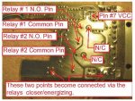
3) With the volt meter setting on DC (and board powered up etc, see #1 above) , place the black lead of the volt meter on pin #5 (gnd) and the red lead on pin #7 (Vcc), you should measure around 12VDC.

If yes to step #3 move to step #4, if not, we'll go from there.

4) With the volt meter setting on AC, place the black lead of the volt meter on pin #5 (gnd) and the red lead on pin #6 (output). Look for a voltage reading of something other then 0V (modulating DC will have a AC value, so use AC scale on DMM).

If yes to step #4, we'll go from there, if not, go to step #5.

5) With the volt meter setting on AC, place the black lead of the volt meter on pin #5 (gnd) and the red lead on pin #4 (oscillator). Look for a voltage reading of something other then 0V (The oscillator waveform will have a AC value, so use AC scale on DMM).
 
Last edited:

jeepwm69

Petty Officer 3rd Class
Joined
May 26, 2010
Messages
84
Ok, so that tiny little black box has 8 pins coming off of it, which are soldered to the board. I'm checking 5 and 7, and should get 12V. Gt it.

If so, on same board, but changing voltmeter to AC, leave black lead on 5, move red lead to 6.

If so, leave black lead on 5, and put red lead on 4, looking for volts again.

That sound about right?
 

sam am I

Commander
Joined
Jun 26, 2013
Messages
2,169
Ok, so that tiny little black box has 8 pins coming off of it, which are soldered to the board. I'm checking 5 and 7, and should get 12V. Gt it.
Yup, but the view as drawn (black box) is a view looking down at the top side of the IC, note the cutout/detents in the IC plastic, once oriented, the pins of the IC follow as per the drawing.

If so, on same board, but changing voltmeter to AC, leave black lead on 5, move red lead to 6.
Yup

If so, leave black lead on 5, and put red lead on 4, looking for volts again.

Nope, well.......Ya can if ya want to and sry is was confusing there by saying ("we'll go from there" I should have said, we'll have to go another direction)...........If you have AC from pins 5 to 6 (step #4), then the oscillator is most likely good (the output waveform is derived from the osc), no need to go to step #5. Only need to go to step #5 (check oscillator) if no AC is present in step #4.

"Where'd we go from here" is the output path to the FET's (blown transistors gm replaced) or the motor's power (seeing this tho in places). etc.

That sound about right?

Yup
 
Last edited:

jeepwm69

Petty Officer 3rd Class
Joined
May 26, 2010
Messages
84
Checked this morning.

When viewed as in the picture above (with the mounting plate oriented to the left side, and the IC/ black box in the top of the picture), I put the negative probe on the top left pin, and the positive probe two pics down, which are 5 and 7 according to the middle pic.

I got nothing. Should I have had the swtich in the "run" position for this?

When I kept the + probe on 7, and touched the - probe to the battery -, I got 12.XX volts.
 

sam am I

Commander
Joined
Jun 26, 2013
Messages
2,169
Checked this morning.

When viewed as in the picture above (with the mounting plate oriented to the left side, and the IC/ black box in the top of the picture), I put the negative probe on the top left pin, and the positive probe two pics down, which are 5 and 7 according to the middle pic.

Sounds right.

I got nothing. Should I have had the swtich in the "run" position for this?

Maybe............try switching into "run" (among any other settings) while measuring 5 and 7

When I kept the + probe on 7, and touched the - probe to the battery -, I got 12.XX volts.

Sounds like the ground is open to the board/IC, maybe going into "run" in the above test will shed some light here.

Perhaps trace the TM's main ground wire/path that leads from the battery neg., does it connect into/through the switch before going to the board? Does an open ground to the board make sense by/according to the path you trace out?

NORMALLY, most designs with IC's (logic, linear, etc, esp. MOS devices/xsters) and such don't un-ground a circuit to shut them off..............Things can get unpredictable.
 
Last edited:

jeepwm69

Petty Officer 3rd Class
Joined
May 26, 2010
Messages
84
I'll try it again with it in "run" after work.

The main ground path connects directly to the board, as do the power leads from battery +.
 

sam am I

Commander
Joined
Jun 26, 2013
Messages
2,169
Hmmm, weird.......

Thing is, the IC will require some voltage difference (guessing at least 12V this case) between pins 5 and 7 in order to work/turn on regardless of where it is ground referenced (battery neg, virtual, etc).

Otherwise put, not getting any voltage across those two pins (5 to 7), the PWM IC isn't going to turn it on, FET's will stay off, motor stays off.

Putting her in run should fire up the IC thinking
 
Last edited:

gm280

Supreme Mariner
Joined
Jun 26, 2011
Messages
14,595
Let me chime in here and see if I can orient you all as to how those two DIPs chips are installed. Looking at the previous picture, the top "little box" on the left hand side is the UC3842N PWM chip. The orientation of that chip is faceing in towards the board. So pin one is the right hand side of that chip on the inter most section. Basically how you drew the chip. So pin 7 is not the last pin on the left, that would be pin 8. Both IC's are oriented toward the inside of the board.
005 m.jpg
So pin 8 is directly across from it and that makes pin 7 next to it toward the out edge of the board. Hope that helps some. Also, see if the ground foil are on the top is reading with the ground foil area on the bottom of the circuit card. Make sure you use sharp probes because the card is coated with clear lacquer to protest it.
 

sam am I

Commander
Joined
Jun 26, 2013
Messages
2,169
Ground path to pin #5-UC3842 from what I assume is the battery neg connection/terminal's (is also the N channel FET's source pins, low side switch, see simplified schematic above) ...... A9R5D3D.jpg


A9R5D3D.pdf
 

Attachments

  • A9R5D3D.pdf
    68.9 KB · Views: 3
Last edited:

jeepwm69

Petty Officer 3rd Class
Joined
May 26, 2010
Messages
84
Let me chime in here and see if I can orient you all as to how those two DIPs chips are installed. Looking at the previous picture, the top "little box" on the left hand side is the UC3842N PWM chip. The orientation of that chip is faceing in towards the board. So pin one is the right hand side of that chip on the inter most section. Basically how you drew the chip. So pin 7 is not the last pin on the left, that would be pin 8. Both IC's are oriented toward the inside of the board.

So pin 8 is directly across from it and that makes pin 7 next to it toward the out edge of the board. Hope that helps some. Also, see if the ground foil are on the top is reading with the ground foil area on the bottom of the circuit card. Make sure you use sharp probes because the card is coated with clear lacquer to protest it.

Gotcha. I did have the correct pins. Just wanted to make sure.

I tried it again this morning with the switch on. Still no voltage reading on pins 5 and 7.

I get 12V on pin 7 when I ground to the battery, but nothing on pin 5.

What is "ground foil"

I probably need to sharpen the pins and make sure I'm getting a good connection on pin 5
 

gm280

Supreme Mariner
Joined
Jun 26, 2011
Messages
14,595
Gotcha. I did have the correct pins. Just wanted to make sure.

I tried it again this morning with the switch on. Still no voltage reading on pins 5 and 7.

I get 12V on pin 7 when I ground to the battery, but nothing on pin 5.

What is "ground foil"

I probably need to sharpen the pins and make sure I'm getting a good connection on pin 5

The "ground foil" is actually the ground traces remaining on any circuit board. And lots of time they manufacture circuit boards with a lot of ground material remaining on the board to help with noise rejection and save on acid material used to remove it. So the majority of the metal material remaining on this circuit board is a ground. So take a meter set to resistance and verify you have continuity between the top side and bottom side of the ground material.
005m2.jpg
So test this area with an area like it on the bottom to verify they read zero resistance....or very very close to zero. Test it with this bottom side
005 m3.jpg
Post your results.
 

jeepwm69

Petty Officer 3rd Class
Joined
May 26, 2010
Messages
84
So, take the + probe, put it on top ground foil or pin 5, and the - probe, and put it on the bottom ground foil, and measure resistance?

Guess I need to study up on my voltmeter as to measuring resistance.

If nothing else, this is getting me some education on using my voltmeter for something other than checking batteries!
 

sam am I

Commander
Joined
Jun 26, 2013
Messages
2,169
gm, not sure about this being ground foil

image_258142.jpg

Here's my take.......

A9R1B4E.jpg A9R1B22.jpg

Thinking (see left image) since that foil becomes common (when relay's are on) with pin #7 (+12/Vcc of the UC3842) it is actually a switched +12V and not a ground foil.
 

Attachments

  • A9R1B4E.jpg
    A9R1B4E.jpg
    73.8 KB · Views: 1
Last edited:

gm280

Supreme Mariner
Joined
Jun 26, 2011
Messages
14,595
gm, not sure about this being ground foil


Here's my take.......


Thinking (see left image) since that foil becomes common (when relay's are on) with pin #7 (+12/Vcc of the UC3842) it is actually a switched +12V and not a ground foil.

You could be right. My thinking was the back side foiled area is corrected to both relay coils and therefore I was assuming, maybe wrongly, that it was ground being how the other coil contacts were independent of the ground. I need to look at it a little more now.

Sure would be great to have an actual schematic for this circuit.
 

gm280

Supreme Mariner
Joined
Jun 26, 2011
Messages
14,595
I hear ya gm, reading traces gets tedious very quickly for sure......


Sam, I have reversed engineered a lot of circuits in my career, but when I had this circuit board to rebuild it, I didn't even try to reveres this circuit. I sure wish I would have taken the time to do that now. It wouldn't have taken too much time to read everything out for a schematic. But water under the bridge now...
 

gm280

Supreme Mariner
Joined
Jun 26, 2011
Messages
14,595
Maybe I can study the pictures I took and see if I can come up with a schematic from them. Not the best was to reverse engineer such a schematic, but without the board and meter, it is the best I can do. JMHO
 

jeepwm69

Petty Officer 3rd Class
Joined
May 26, 2010
Messages
84
Want me to send it back to you with the switch? I'd be happy to pay you for the work, just because at this point I'm determined to fix it.

I have another motor so not in any hurry to get it back.
 

gm280

Supreme Mariner
Joined
Jun 26, 2011
Messages
14,595
Want me to send it back to you with the switch? I'd be happy to pay you for the work, just because at this point I'm determined to fix it.

I have another motor so not in any hurry to get it back.

That could be a second option. However, can you ask the manufacture if you could get a schematic diagram for the circuit board because you are trying to get it running again. Since it is an older version, that they no longer manufacture, maybe they will give you the schematic or direct you to where you can find one. Try that first.
 
Top