Mercury 7.5 HP Motor Refresh (1969 model year)

racerone

Supreme Mariner
Joined
Dec 28, 2013
Messages
36,311
??---Where is the lower cowling ?-You might want to install that first !
 

tpenfield

Moderator
Staff member
Joined
Jul 18, 2011
Messages
17,711
New Year's day update . . .

Happy 2017 everyone :)

I am doing some prep work for painting and continued assembly, taking care of some issues . . .

The bottom cowl is 'suspended' from the drive shaft housing using 3 rubberized mounts . . . 2 in the front and 1 in the rear. The front mounts look like this

cowlmount1.png

At least it is supposed to . . . The mounts on my motor had fractured where the bottom plate meets the rubber base, as shown below on the right.

IMG_9340.jpg

These parts are 'NLA', so I had to figure out a way to fix these parts. On the left (above) I came up with a quick solution that should be OK, not perfect, but OK, just by screwing in the plate to the rubber base. We shall see how they hold up, but anything is better than the broken mounts that have been there.

Here is the repaired mount attached to the drive shaft housing.

IMG_9341.jpg

The rear mount is of a different design and is still in good shape.
 

tpenfield

Moderator
Staff member
Joined
Jul 18, 2011
Messages
17,711
I spend much of New Year's day doing some painting of the various pieces of the motor (and watching football). Here are the pieces/parts with the Zinc Phosphate primer applied.
IMG_9342.jpg


IMG_9344.jpg


IMG_9345.jpg


The primer still seems slightly tacky after about 16 hours. I did apply some heat to help with the drying/curing process, but maybe they need more time.

As I go through this motor, it appears that it was taken apart previously, as not all the correct hardware is in the right places. Myself, I am still trying to figure out where a few pieces of hardware are supposed to go. I 'forgot' to take lots of detailed pictures when I was taking things apart. So, there will be a bit of trial/error.
 

Attachments

  • IMG_9343.jpg
    IMG_9343.jpg
    86.4 KB · Views: 1
Last edited:

tpenfield

Moderator
Staff member
Joined
Jul 18, 2011
Messages
17,711
Well, I could not resist doing the first finish coat (black), which I needed to do before staring to put the rest of the motor together.

Engine cover/cowl . . .
IMG_9346.jpg

Lower cowl and skirt
IMG_9347.jpg

Transom bracket
IMG_9348.jpg

Powerhead/Drive shaft housing
IMG_9349.jpg

I used Rustoleum Universal Paint/Primer-in-one. (Gloss Black). It covers very well with a thin coat. My plan is to give the externally facing surfaces a light sanding once it is all together and then a final coat of paint.

I also have a decal set, once it is all done.

I had to improvise a painting/drying area, since it is winter and my garage is only about 40 F. So, I sprayed the paint in the garage and then heated the laundry room and sucked the fumes out through the garage and out the side window. It seems to be working OK.

The paint will need to setup for a few days . . .
 

tpenfield

Moderator
Staff member
Joined
Jul 18, 2011
Messages
17,711
I have been trying to sort through the various hardware and fasteners to make sure I get them where they are supposed to go. My bad for not better categorizing during disassembly. I did find 1 or 2 fasteners for the lower cowling that were in the wrong place from a prior re-build, so I got that sorted out.

Anyway, I have most of it figured out, but these 2 spacers/bushings have me wondering . . . I have searched through the assembly diagrams and parts lists that are available online, yet have not been able to isolate what these are for/where they go?

IMG_9350.jpg

They are non-machined, roll-formed spacers . . . but they could be called 'bushings' (maybe) :noidea:

Any help here? T.I.A.
 

tpenfield

Moderator
Staff member
Joined
Jul 18, 2011
Messages
17,711
I think I have these spacers ID'd . . .

23-39578 . . . Front Cover Spacer for cowl assembly.
 

tpenfield

Moderator
Staff member
Joined
Jul 18, 2011
Messages
17,711
I got the bottom cowl and the transom/saddle assembly installed today. I'll be waiting on a few replacement parts before doing more, but it is starting to look like an outboard motor again :)

IMG_9352.jpg


IMG_9354.jpg
 

tpenfield

Moderator
Staff member
Joined
Jul 18, 2011
Messages
17,711
More progress . . . here and there.

The parts came for the Merc, so I was able to do a few more things.

There should be 2 specialized nuts for the steering handle pivot . . . one of the nuts was missing when I dis-assembled it. So, for $15 :eek: :rolleyes: I was able to order one . . . it is an NLA item.

Here is the steering handle now properly installed (I hope). IMG_9360.jpg


I also bought a new trim pin, which had been missing since I bought the motor. $32 :eek: as I believe it too is NLA. IMG_9357.jpg


It will be nice to be able to trim the motor though.

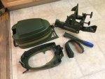
The interface pipe to the water pump had come off and the fitting portion of the water pump housing had cracked a bit. So, I got some adhesive holding it together. IMG_9358A.jpg


There was also some hardware missing from the fuel line connector. The bolt is NLA as it is a #8 1-3/8" and there did not seem to be any direct generic replacements. There is a molded in insert for where the nuts should go, so I ended up using #6 stainless hardware w/ nylock nut in order to fit into the inserts. IMG_9355.jpg


Getting the fuel connector and the carburetor installed is fairly tricky . . . it seems like the fuel line connector likes to go first, then you can install the carb.
IMG_9359.jpg


Once the water pump repair has set up, I'll be able to install the lower unit and do a few final things.

My plan is to run the motor in a Homer Bucket (or something similar) to be sure it actually runs before I do the final painting and decals.

:noidea: not sure I I should do anything special for breaking in the new piston rings :noidea: I had planned on running a little higher oil mixture (about 30:1, instead of 50:1). all the engine internals are pretty well soaked with 2-cycle oil from the assembly process.
 

tpenfield

Moderator
Staff member
Joined
Jul 18, 2011
Messages
17,711
I have the lower unit on and did a bit more work connecting the choke lever.

IMG_9362.jpg

There is a wire spring that assists the neutral throttle governor . . . it came off during the disassembly many months back . . . although I'm not sure how it did, because it seems to be nearly impossible to put back on.

I think I am going to need an angled needle nose pliers to get it back on.

The good news is that I seem to have all the remaining fasteners accounted for . . .
 

tpenfield

Moderator
Staff member
Joined
Jul 18, 2011
Messages
17,711
Another Update:

I got the lock-out spring installed. I just removed the lock-out lever and was able to insert the spring and then re-install the lever.

I needed to get the spring installed before installing the cable and ignition kill switch.

IMG_9363.jpg

Fortunately, I had taken a picture of the wiring connections during disassembly, so no guess work for the wiring.

Here is a picture of the cowling installed.

IMG_9365.jpg

Just waiting to test run the motor to make sure all is good before final painting and decals.
 

tpenfield

Moderator
Staff member
Joined
Jul 18, 2011
Messages
17,711

merc850

Commander
Joined
Jul 7, 2010
Messages
2,026
I was just going by the picture at 7:25 and I didn't see Nr.19. It's no big deal if you leave the ext. fuel line connected. image_257296.jpg
 

tpenfield

Moderator
Staff member
Joined
Jul 18, 2011
Messages
17,711
Oh, OK . . . I never noticed it being there or not there. I'll take a look, as I have never taken the connector apart.
 

tpenfield

Moderator
Staff member
Joined
Jul 18, 2011
Messages
17,711
I see the parts diagram for my engine (1969 model) shows P/N 32454 as the "check unit", but does not show any internal parts. The few years after this motor shows the P/N 22833 as the check unit and some internal parts.

Is the 32454 check unit different than the 22833?
 

merc850

Commander
Joined
Jul 7, 2010
Messages
2,026
I am only guessing but they probably expanded the definition of check unit and show its individual components for later motors.
 

tpenfield

Moderator
Staff member
Joined
Jul 18, 2011
Messages
17,711
I am only guessing but they probably expanded the definition of check unit and show its individual components for later motors.

Understood. The pictures that I can find online of the 32454 check unit do not have any internal parts visible, yet pictures of the 22833 check unit do. I do not get any draining of fuel when I disconnect the fuel line. So, I'm wondering if there is a different internal mechanism on the 32454 vs. the 22833 ?
 

tpenfield

Moderator
Staff member
Joined
Jul 18, 2011
Messages
17,711
UPDATE:

I hooked up the fuel tank and ran the engine for the first time after the rebuild. It sure has a lot of compression versus what it used to have :eek:

I added some extra oil to the fuel for 'break-in' purposes. . . probably about 30:1 instead of the regular 50:1

I varied the speed of the engine frequently and shifted it into forward and reverse - no issues there. I still have to adjust the throttle linkage a bit, and I am wondering if I will need to adjust the timing and/or the fuel mixture :noidea: I did not touch either during the rebuild. Setting the timing is a bit of a mystery to me, but perhaps I should at least check into it.

Here are a couple of pictures running it in a barrel on a nice 33 F degree day :)

IMG_9418.jpg

IMG_9425.jpg


Here is a short video of the engine running.


tpenfield

Moderator
Staff member
Joined
Jul 18, 2011
Messages
17,711
Another Update . . .

I ran the engine some more today. I noticed that it was misfiring a bit, so I pulled the spark plugs to check them. It turned out that the gap on one of them had closed up pretty much . . . probably when the plugs were out during the rebuild, etc. Anyway, I reset the gap on both plugs and now it runs really well.

After the engine had run for a while, I checked the idle RPM with my induction tach and set the throttle stop. The motor seems to like to go down only to about 1200 RPM as the minimum idle speed. Not sure if there is a spec on this setting :noidea:

Anyway, it is set at about 1200 RPM and seems to work fine.

Here are a couple of pictures and a video of it running today.

IMG_9451.jpg

IMG_9450.jpg

It seems to idle and run better than it did before . . .

 
Top