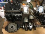
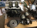
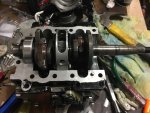
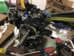
Mercury 7.5 HP Motor Refresh (1969 model year)

tpenfield

Moderator
Staff member
Joined
Jul 18, 2011
Messages
17,711
Quick Update - Salt/calcium cleaning

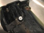
I got some salt eliminator to clean out the water jackets and side panel of the powerhead, while the engine is apart. One area in particular was the 'Flush' tube and plug fitting.
IMG_9187.jpg

I had not been able to remove the Flush Plug since I have owned the engine (about 3 years), but I wanted to see if I could get it back into annual operation. The impact driver did a nice job in loosening the plug. The calcium/salt was packed solid inside the flush tube. The salt 'impaction' extended about 2" up the tube. I drilled out most of it from the top of the housing, but the drills that I had would not go all the way to the plug fitting. There was about 1/4" of hardened salt remaining, which blocked the tube. I poured salt-away in the tube and let it sit overnight - still nothing. I used some light drilling in the fitting end to see if I could 'break through' to the other side.
IMG_9184.jpg

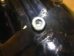
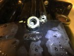
Finally, I got a right angle scribe and worked into the salt, which was more like sandstone and got the flush tube cleared. :thumb:
IMG_9186.jpg

I guess I should make the salt flush and annual event going forward :)

As for the powerhead and overall engine assembly, I still have to remove the remnants of the gaskets from all of the mating surfaces. That seems to be more difficult than the salt blockage :rolleyes:

Any tips/tricks there on gasket remnant removal? :noidea:
 

tpenfield

Moderator
Staff member
Joined
Jul 18, 2011
Messages
17,711
I have begun putting the powerhead back together. I honed the cylinders to get rid of the glaze on the cylinder walls and have got all of the old gasket material off of the mating surfaces (no easy task). I put the new rings on the pistons and pressed the bearings into the upper carrier, etc.

IMG_9200.jpg

One question that I have at this point is if there is an easy way of getting the pistons back into the cylinders. it looks a bit more tricky than installing a piston into the 4-stroke engine, so I am wondering if there is a specific technique that seems to work best. :noidea:

IMG_9201.jpg
 

racerone

Supreme Mariner
Joined
Dec 28, 2013
Messages
36,311
See those cutouts on the bottom of the cylinders ?----Those are for special factory ring compressors.-----But a small screw driver / experience / patience also works for me.---I do have those ring compressors too.
 

tpenfield

Moderator
Staff member
Joined
Jul 18, 2011
Messages
17,711
Thanks racerone . . . a couple of small screwdrivers will have to do. Maybe I can use a clamp to hold them to the piston while I 'wiggle' them in.
 

tpenfield

Moderator
Staff member
Joined
Jul 18, 2011
Messages
17,711
Well, I got one piston in . . . the lower piston . . . not quite sure how it did it, but once I got the first ring into the cylinder, the other 2 were not too hard. The upper piston just does not seem to want to get started.

It seems when I get a good 'pinch' on the rings to close them up, I don't get much downward pressure to get the piston into the cylinder.

Tried for about 3 hours today . . phoooey :rolleyes:
 

tpenfield

Moderator
Staff member
Joined
Jul 18, 2011
Messages
17,711
After trying a little more, it seems that the piston rings are hanging up at the opposite / adjacent side to where I am 'pinching' the piston rings closed with my screwdrivers. This is more of an obstruction that's what I experienced with the bottom cylinder.

Not sure if there are any tricks to get the rings to close up a bit tighter ?

I have also been using a couple of small wood chisels instead of the screw drives to hold the rings closed, since they are stiffer that the screw drivers. Still no luck. My next step is to get a C clamp to hold the tools tight to the piston an hopefully close up the rings a bit more and allow my hands to be free to wiggle the piston in.

Not sure if there is any trick or method to positioning the rings so the they close up better. So far, I have been positioning the gap on opposite sides of the piston and a bit off center of the wrist pin.
 

tpenfield

Moderator
Staff member
Joined
Jul 18, 2011
Messages
17,711
After doing some online searching, I came across some information about piston rings having a taper to them, at least some of them do. Not sure if my OEM Mercury rings would have a taper to them :noidea:

If so, I guess I'd have to figure which direction the taper goes and which way is up :). Fat end of the taper would go towards the top of the piston?
 

tpenfield

Moderator
Staff member
Joined
Jul 18, 2011
Messages
17,711
Also, came across info about pins in the piston groove for ring orientation. I didn't notice any pins on the Pistons, not that I was looking, but can certainly look for them now.
 

racerone

Supreme Mariner
Joined
Dec 28, 2013
Messages
36,311
No such thing as tapered rings on your little Mercury. !---------I can not believe you actually got one piston in the bore when you say you do not know about the little pins .
 

tpenfield

Moderator
Staff member
Joined
Jul 18, 2011
Messages
17,711
No such thing as tapered rings on your little Mercury. !---------I can not believe you actually got one piston in the bore when you say you do not know about the little pins .

:D Must have been my lucky moment that the rings lined up with the pins after numerous attempts, because the piston went in rather effortlessly. Now I know what to do on the other piston :thumb:

Thanks for confirming these finer points of assembly :)
 

tpenfield

Moderator
Staff member
Joined
Jul 18, 2011
Messages
17,711
I did it !!! :D :D :D :clap2:

IMG_9205.jpg


IMG_9206.jpg

Once I saw the pins in the piston groves, I was able to line up the rings and get them to close up. It just so happens that on the other piston, I was positioning the rings in about the right place, so it must have been a matter of chance that they would be right.

Anyway, the assembly continues.
 

tpenfield

Moderator
Staff member
Joined
Jul 18, 2011
Messages
17,711
It seems like nothing goes back together the way it came apart . . . As I secure the top bearing carrier to the crankcase, the crankshaft binds up. If I loosen the 4 bolts holding the carrier about 1/4-1/2 turn, the crankshaft loosens up nicely.

So, I'm thinking that with the new 204 bearings, I may need a couple of extra shims on the top bearing carrier. Does that sound about right ? :noidea: I tried several times to get the 204 bearing to seat a little more into the bearing carrier, heated the carrier up and pounded it in, but that seems to be all that it will go. From the pictures that I took during disassembly, it looked like the bearing was a bit more recessed into the carrier, but it is hard to tell.
IMG_9207.jpg

I'll see if I can get some more shims. Currently there are 2 shims there, which were original.
 

racerone

Supreme Mariner
Joined
Dec 28, 2013
Messages
36,311
It is NOT a problem with the upper bearing.---------And be carefull about adding more shims.-------Best to go over your work so far.--------Bearings are precision made to a standard dimension !
 

tpenfield

Moderator
Staff member
Joined
Jul 18, 2011
Messages
17,711
It is NOT a problem with the upper bearing.---------And be careful about adding more shims.-------Best to go over your work so far.--------Bearings are precision made to a standard dimension !

Yes, I am thinking that either I have not got the bearing to seat properly, or as you say something is amiss further down the line. I will go back through the assembly.

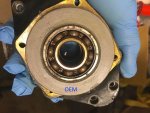
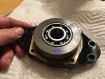
Here are an 'old' and 'new' picture of the bearing carrier. I cannot really tell if it is seating fully. It looks close.

OEMBearingCarrier.jpg

NowBearingCarrier.jpg

The new bearing sits ever so slightly above the level of the bearing carrier face . . . I was thinking perhaps it should be flush :noidea:
The assembly originally has 2 shims . . . not sure of their thickness. I think that I am off by about 0.010" in terms of getting the crankshaft to turn freely.
 

tpenfield

Moderator
Staff member
Joined
Jul 18, 2011
Messages
17,711
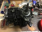
Well, I disassembled the crankcase half and then fitted the top bearing carrier to the remaining crankcase. things seemed to line up better and I was able to reassemble the crankcase with the crankshaft spinning freely.

I put the flywheel on temporarily to be able to turn the crankshaft.

IMG_9210.jpg
 

tpenfield

Moderator
Staff member
Joined
Jul 18, 2011
Messages
17,711
I *think* what happened during the initial assembly of the crankcase is that the lower bearing was riding up a wee bit in its slot and when I bolted the crankcase halves together, the lower bearing was trapped out of position, so that the crankshaft was also riding a bit higher inside the case.
 

tpenfield

Moderator
Staff member
Joined
Jul 18, 2011
Messages
17,711
Snowy Day Update:

I have been doing a bit more work on assembling the motor and seem to have run into an issue . . .

The ignition assembly is supposed to slide down over the top bearing carrier/cover and have enough play to be able to pivot for the timing advance as governed by the throttle linkage.

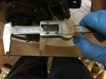
Well the ignition assembly does not seems to want to slide over the bearing carrier, and if I were able to get it to go together, it probably would not be able to rotate at all. I checked the dimensions of the bearing carrier vs the ignition assembly bushing and sure enough there is a few 0.001's discrepancy.

Here is the bearing carrier . . .
IMG_9286.jpg


Here is the ignition assembly bushing . . .
IMG_9288.jpg

This does not seem quite right . . . I would think it should be the other way around :noidea:
So, I figure that I am missing something that may be obvious, but I am at a loss as to what that would be. The only thing that I can think of is that I am working in the garage and it is about 35 F degrees there . . . so I'm wondering if temperature has something to do with it, but that would not make sense.

Anyone have an idea as to what the issue may be?
 

tpenfield

Moderator
Staff member
Joined
Jul 18, 2011
Messages
17,711
Update:

I got the ignition assembly to go on and settle into place. I put the flywheel on and fastened it down. However, the flywheel is hitting the coils when I turn the flywheel. Not sure what the clearance should be between the magnet and the coil, but it seems that they shouldn't be hitting :noidea:

It does not look like there is any adjustment for the coils, but maybe there is. . . :noidea:

This engine sure does not want to go back together . . . :rolleyes:
 

tpenfield

Moderator
Staff member
Joined
Jul 18, 2011
Messages
17,711
OK, I got the magneto issues resolved (I think) . . . I took the flywheel and the ignition assembly off and then re-installed everything. I don't think I had the spring screws that hold the ignition assembly down tight enough and it was causing the coil to hit the flywheel.

Everything seems OK now . . . so onto the next steps.
 

tpenfield

Moderator
Staff member
Joined
Jul 18, 2011
Messages
17,711
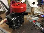
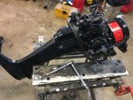
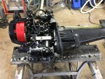
Making some progress . . .

IMG_9291.jpg

It is starting to look like a boat motor again :)

IMG_9292.jpg
 
Top