Tilt/Trim Motor stator field coil windings connections

DavidLewis

Cadet
Joined
Jan 27, 2016
Messages
17
Hi all. My 3-wire tilt/trim motor from a 1979 Mercury 70hp doesn't work. It doesn't rotate when I connect either the green or the blue wire to +12V while the black wire is connected to battery ground. ​I've dismantled the motor, done all the first-stage checks (looking for continuity / shorts between the various windings and metalwork on armature and stator) and as far as I can tell, it all checks out OK. (I don't have a growler though.)

fetch


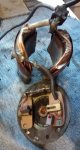
Looking at the internal wiring of the motor, I'm wondering whether a previous owner has attempted an incorrect repair. If I describe what I can see, can anyone tell me whether it's supposed to be internally wired like this please?

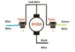
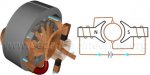
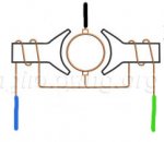
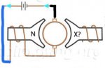
It's a three-wire motor. The green wire is attached to one end of the first field winding. The other end of that field winding has a link wire, which runs to the second field winding on the opposite side of the casing. The other end of the second field winding has a blue wire attached. One of the brushes is connected to the link wire that joins the first and second field windings. The other brush is connected to the motor end plate, which has a black wire bolted to it. I've drawn a diagram:


fetch

It means that only one of the field windings (on only one side of the motor!) will be energised when, say, the blue and black wires are connected to the battery. This doesn't seem very likely to me - there surely won't be much of a magnetic field across the armature in this case?
Is that the way it's supposed to be?

Thanks for your help,
David
 

Attachments

  • photo239652.jpg
    photo239652.jpg
    64.3 KB · Views: 1
  • photo239654.jpg
    photo239654.jpg
    18.7 KB · Views: 1

sam am I

Commander
Joined
Jun 26, 2013
Messages
2,169
It looks correct........It's your basic series wound dc motor. One field (forward/blue) is wound one direction and the other field (reverse/grn) is wound the opposite.

Put the armature back in the brushes path/bushing and measure continuity from blue ---> blk and green---->blk. Should see basically 0'ish (zero) ohms
 

DavidLewis

Cadet
Joined
Jan 27, 2016
Messages
17
Thanks for your reply Sam. Yes, I do get a fraction of an ohm for each of the continuity tests you describe.

I still can't get my head around what the magnetic field looks like when only the one field coil is energised. That will create a (say) North pole in the gap between that coil and the armature. But there will be no South pole generated by the other field coil, because no current is flowing in it.

What am I misunderstanding?
 

Chris1956

Supreme Mariner
Joined
Mar 25, 2004
Messages
27,211
Those motors can have a bi-metal temp sensor, inside the casing, although I could not see it in the diaghram. These can get some dirt between the contacts, and you will not have continuity.
 

merc850

Commander
Joined
Jul 7, 2010
Messages
2,032
Here's the wiring diagram that should help, the solenoid changes the current flow power-trim-wiringsmall.jpg
 
Last edited:

sam am I

Commander
Joined
Jun 26, 2013
Messages
2,169
Thanks for your reply Sam. Yes, I do get a fraction of an ohm for each of the continuity tests you describe.

I still can't get my head around what the magnetic field looks like when only the one field coil is energised. That will create a (say) North pole in the gap between that coil and the armature. But there will be no South pole generated by the other field coil, because no current is flowing in it.

What am I misunderstanding?

It'll try to explain as best I can but Google is always a good source too!!

It has to do with the timing of a particular armature winding's (poles, there are like 6 or 8 I think) relative to the particular (forward for example) field winding. The brushes power a particular armature winding (pole) of course and sit 180 apart from one another but can be rotated 360 degrees about the armature's stator by spinning the end cap they sit. Otherwise put, the brushes can rotate about an axis relative to the armature's stator timing them relative to a particular armature's stator which in turn is timing the particular energized pole.

They (the brushes) however are fixed when the end cap is screwed in place BUT, such that the timing of the pole energized is slightly ahead (or behind) the relevant energized field (forward or reverse). When the specific pole of the armature energizes, it of course begins being attracted toward the field's field (forward for example), at a certain point in the stator's rotation, the next in turn pole in the armature becomes energized, rinse lather repeat.
 
Last edited:

DavidLewis

Cadet
Joined
Jan 27, 2016
Messages
17
No Title

It'll try to explain as best I can but Google is always a good source too!!

Your explanation is very good, and I truly thank you for taking the time and trouble to write it. I'm pretty sure I understand your explanation, and the theory of how a series-wound DC motor works.

I don't understand how the motor I have in front of me can work in theory (because I know it doesn't work in practice!). Neither do I understand how the field windings in 3-wire reversible DC motors are actually (supposed to be) wound / connected :(

My turn to explain what I don't understand. With the aid of diagrams borrowed from http://www.learnengineering.org/2014/09/DC-motor-Working.html here is a standard series-wound DC motor:

fetch


Note that it's a 2-wire motor (one rotation direction only). It has two poles produced by two field windings. When it's running, BOTH field windings are energised - one produces a North pole, and the other a South pole.

Now, here is my motor:

fetch

You can see the three wires, and see how the armature is connected.

When the Blue and Black wires are connected to tilt the motor up, this is where the current flows:

fetch


So the North pole is created as with the standard 2-wire motor. But there is no South pole because the other winding has no current flowing through it because the green wire isn't connected to anything.

So my question: is this really how "normal" 3-wire tilt-trim motors are configured internally? Where is the missing South pole?

I'm really hoping to understand this - thanks for sticking with me this far!
 

Attachments

  • photo239680.jpg
    photo239680.jpg
    38.4 KB · Views: 0
  • photo239681.jpg
    photo239681.jpg
    25.5 KB · Views: 0
  • photo239682.jpg
    photo239682.jpg
    26.6 KB · Views: 0

sam am I

Commander
Joined
Jun 26, 2013
Messages
2,169
So my question: is this really how "normal" 3-wire tilt-trim motors are configured internally?

I think for yours, yes. However, my circa 92 3 wire has if I recall correctly 4 brushes total.

Where is the missing South pole?

"B" fields, force vectors and the right hand rule. My autocad skills are being tapped here..............Given me a sec, I'll try to draw this (your) particular motor .
 
Last edited:

sam am I

Commander
Joined
Jun 26, 2013
Messages
2,169
Not sure how well you can see the vector arrows (dwg ---> pdf loss, zooming helps. 3D might help, maybe later) and i think I have all the vectors correctly for specific directions of current (it been a while, arrow tails [crosses] show direction of current entry) but one field at a time creates a "B" field and the particular energized armature winding also has a field about it. The two forces combine to attract (or repel) as they cut through each other as the commutator energize the next up armature winding as it is spinning.

index.jpg
 

Attachments

  • motor vectors.pdf
    96.4 KB · Views: 0
Last edited:

DavidLewis

Cadet
Joined
Jan 27, 2016
Messages
17
Once again Sam, thank you so much for your efforts.

I understand about the field created by the armature windings interacting with the field created by the stator windings, creating a rotational force. For that force to be sufficient to rotate the armature, the strength of the magnetic flux created by the stator windings needs to be significant. In all motors I have researched, the stator flux is kept strong by the stator having at least two poles (one North and one South). Indeed, if you do a Google image search for "single pole DC motor" you won't find any at all - ALL the pictures show motors with at least two stator poles (North and South), just like in the attached link from https://en.wikipedia.org/wiki/DC_motor
Ejs_Open_Source_Direct_Current_Electrical_Motor_Model_Java_Applet_%28_DC_Motor_%29_80_degree_split_ring.gif


I think the reason that stator poles come in (at least) pairs is that to achieve sufficiently high flux strength, the magnetic field needs to "travel" between two poles (see the yellow lines in the Wikipedia animation) with the armature sitting within that field between the two poles.

My motor, with only the green or the blue wire connected to +12V, has only ONE POLE next to the armature. So it doesn't work because the strength of the flux is not sufficient for a turning force to be produced on the armature because the flux doesn't travel between two poles either side of the armature. One pole DC motors don't exist, because they don't work. Just like my motor.

Please tell me I'm not crackers :)
 

Chris1956

Supreme Mariner
Joined
Mar 25, 2004
Messages
27,211
Gee, lots of design questions for a motor that is 40 years old. Check for continuity thru the fields, and none to the case. Do the same for the commutator. Check for continuity thru the brushes to the commutator. Without a growler, I do not know how to check individual windings on the armature.

If she fails any of those tests, and a fix is not evident, look for an aftermarket replacement. ARCO used to sell them. They came as an assembly with the upper reservoir.
 

sam am I

Commander
Joined
Jun 26, 2013
Messages
2,169
David,

No, not crackers and I consider that it would be less powerful (half as much)lacking running the other side simultaneously but depending in the current (amps) through the one side at design time, enough torque was be created knowing the work it had to do.....


Serie_Shunt_Coumpound.png


A, Shunt B, Series C, Compound f, Field coil


https://commons.wikimedia.org/wiki/F..._Coumpound.png


The other thought is it suppose to be a two wire series wound? Did merc have a three or two wire trim setup that year? Does it look like the stock trim motor lined out in their service manual? Earlier you suggested the PO might have modified it, is their evidence of that? Like perhaps non factory looking kluge looking connections/soldering and the like?

Perhaps the PO added the jumper and center tapped it with the blk/ground wire?

So if you remove the jumper/center tap that ties the fields and run it like....

+/- --------Fa------Ba-------A-------Bb-------Fb-------- -/+

where Fa = Field winding A, Ba = Brush A, A = Armature, Bb = brush B, Fb = Field B and +/- = Battery polarities

Does it run? does it reverse?

Can test the armature somewhat by doing a continuity tests

1) From the axle/drive shaft to the commutator contacts? = open/high resistance, like in the meg ohms

2) From the armatures iron cores (poles) to the commutator contacts? = open/high resistance, like in the meg ohms

3) From commutator contacts to commutator contacts = zero'ish ohms
 
Last edited:

gm280

Supreme Mariner
Joined
Jun 26, 2011
Messages
14,597
Have you actually tried to apply 12 volts to the motor itself out of the circuit? If that doesn't spin it up in both directions, time for a new one. Clean the armature before reassembling it and see what happens. I would also grease up the bearings or bushings while apart. JMHO!
 

sam am I

Commander
Joined
Jun 26, 2013
Messages
2,169
gm/chris both make a good points and we're assuming you've been doing/knowing the basic trouble shooting but perhaps something simple is being overlooked.

On the bench........


As currently wired/you found it and it's fully assembled, I would assume you checked that the shaft spins freely? I'm sure you did

But........as with what gm suggested and with the good continuities you've checked/stated above

When applying 12V to a blu or grn wire and ground to the blk wire, you stated it isn't running/working. HOWEVER, I never asked and you never stated a very basic thing, when power is applied and it isn't working/spinning, it.........

a) draws no current? (chris's post #4 and the like...open thermal switch, gm post #14....dirty brushes/commutator contacts)
b) draws tons of current? (post #13 and the like.......shorted armature/field, PO modified/hacked it)
 
Last edited:

DavidLewis

Cadet
Joined
Jan 27, 2016
Messages
17
You guys raise some good points, as always. In answer to the suggestions:

Check for continuity thru the fields, and none to the case. Do the same for the commutator. Check for continuity thru the brushes to the commutator.
I have done that. I have no way of knowing the accuracy of my digital multimeter for reading very low resistances - with the multimeter leads touching each other it reads 0.2 ohms. Each of the field windings reads about 0.3 ohms, with no continuity to the case. The resistance between opposite commutator segments reads (from memory) about 0.4 ohms, again with no continuity to the metal of the armature on any of the segments. I can't remember the resistances between each of the adjacent commutator segments, but it seemed sensible when I took it.

If she fails any of those tests, and a fix is not evident, look for an aftermarket replacement.
Have you actually tried to apply 12 volts to the motor itself out of the circuit? If that doesn't spin it up in both directions, time for a new one.
Yes, that was my first test, using jump leads direct to the (charged!) battery. I'm confident that a new motor would work fine, but where's the fun in that? ;)

I would assume you checked that the shaft spins freely?
Yep, I've reassembled it now, and the shaft spins freely. In fact, it even generates a few millivolts when spun in one direction, and a few negative millivolts when spun in the other direction. I guess there must be some residual magnetism left in the stator poles.

When applying 12V to a blu or grn wire and ground to the blk wire...
...the motor takes enough current to cause a spark when I connect the jump lead to the battery. I don't know how much current, because my meter only goes up to 10 amps which will be insufficient. At these high currents, it's difficult for me to determine whether there are short circuits or not.

is it suppose to be a two wire series wound?
A two-wire series wound (NOT permanent magnet) motor would run only in one direction.

Perhaps the PO added the jumper and center tapped it with the blk/ground wire?
This is really the crux of why I posted in the first place - I was hoping that someone would be familiar enough with the internals of these motors to tell me whether it is supposed to be the way it currently is.

So if you remove the jumper/center tap that ties the fields and run it like....

+/- --------Fa------Ba-------A-------Bb-------Fb-------- -/+
That is a great suggestion, and one that I will do this weekend. I can't think of a better next step. It would be, as far as I can conclude so far, totally non-standard. But I actually suspect it will run like that. I'll let you know!
 

sam am I

Commander
Joined
Jun 26, 2013
Messages
2,169
Find anything odd doing this?

https://www.youtube.com/watch?v=qNV7TylIzSY

BTW and FWIW, I dug through my pic's of when I had mine apart........Standard "square motor" 3 wire but as I said, it's a circa 92 - 4 brush unit.

So the reason I post this pic, is it raised a question in my mind of........"Should ALL (any year'ish merc) three wire units have had 4 brushes"?

Which then transcends into your world of "Why would I then have a 3 wire with only 2 brushes" Perhaps a alien conspiracy of motor snatching to take certain leverage over a aftermarket merc market? (((Insert dramatic music here))))) Hmmmm??...........J/K but I agree, what fun would it be to just pitch it at this point? Inquiring minds with little or nothing to do otherwise, need to know!!
SAM_3616_a.jpg
 
Last edited:

DavidLewis

Cadet
Joined
Jan 27, 2016
Messages
17
Hi guys. I thought I'd report back with a conclusion to this thread...

Firstly, I'm pleased to report that my 40-year-old tilt/trim motor now works well :happy:. I followed Sam I Am's suggestion in post #13, and removed the "centre tapping" wire from between the two field windings and brought it outside the motor casing. So my 3-wire motor is now a 4-wire motor!

To operate the motor, the current always flows the same direction through the rotor (via the brushes) but I choose the direction the current flows through the stator's field windings to raise / lower the engine. Both field windings are still connected in series, and both are now used when the motor is operating. I have a pair of relays on order.

But, annoyingly and embarrassingly for me, it seems the reason why the motor wasn't running in the first place was a defective 12V battery :facepalm:. The battery read 12.6V no-load, and there was a spark when I connected the motor, so I didn't suspect there was anything wrong with the battery. I'm older and wiser now...

I had already modified the tilt/trim motor as above, so I didn't get to test the motor in its as-found (single energised field winding) arrangement with the new battery. This is an unsatisfactory situation, but as the motor is working well I'm not going to change it now!

Thanks to everyone for your helpful suggestions along the way.
David
 
Top