Stator Rewrap

Pusher

Lieutenant
Joined
Sep 2, 2014
Messages
1,273
Well, I am rather stumped. I couldn't get enough of the hard plastic coating off to get a good idea of what is going on. The yellow wires continued to be brittle the full length into the case (as well as corroded). You have to love how a manufacturer will make something that could last a hundred years, then add a wire that will make it 30. The red, blue, and black wires are still pliable and valid. The yellow ones are just trash.


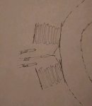
There's a yellow wire going off in each direction.
The red and blue wires look to be going to the same way which is what's confusing me a bit.
The black ground looks to be going to the round thing in the lower right of the stator. (That would be the ground coming up and soldering to the stator wrap wire before I removed the solder joint.)
The magnet wire itself looks like it is the size of 6lb monofilament fishing line. VERY tiny.... Why so small?

I am hoping to have a plan of action for tomorrow and either repair this sucker (if possible at this point) or start re-wrapping it.Honestly,
I am half tempted to stick the whole thing in a fire and cook the plastic off. If I did that, then I'd order magnet wire and the wells solder tool tomorrow.

Help/advice is appreciated.

Seems odd. The red/blue leads dive off to the right outside of both coils 11 & 12. Is that so they could be taped to the coil for support before going back to 11 & 12 for soldering?
 

gm280

Supreme Mariner
Joined
Jun 26, 2011
Messages
14,597
Well Pusher, if nothing else you are persistent.

Seems if you look at the replacement setup, you see a pattern with every other coil being wrapped in reverse of the previous one. And that is because it has to produce an AC output current. As the flywheel magnets pass by each coil it produces a magnetic field which produces a voltage, and then it reverses that field and voltage as the magnet passes the next coil. However, I think you may know that it is not wires in a series sequential order. I think it is wired cross wise. Meaning one coil on one side is attached to a coil directly across from it as well. But that is only my guess. I think you will see as you carefully remove the burnt wires now. So the number of wraps per coil, and the direction of the wraps (CW or CCW) and how it goes to the next coil is the critical info you will certainly need to know. But once you figure out the number of wraps and direction and the next coil it goes to, I think it will be fairly easy to see the pattern.

When you buy the magnet wire, if you don't get it long enough, make sure where you splice the wires together, you varnish or use something to insulate them. JMHO
 

GA_Boater

Honorary Moderator Emeritus
Joined
May 24, 2011
Messages
49,038
What does the wiring diagram show for the 2 yellows, the two blues sand 2 red connections - To what are they connected?
 

Pusher

Lieutenant
Joined
Sep 2, 2014
Messages
1,273
Thanks guys for the input. In post 39, I have the number of wraps and direction of wraps listed, as well as where to start. I also thought they would cross the stator body and there would be multiple leads, but as it turns out, the yellow wires were the ends of one long copper wrap that alternated CW and CCW. I'm not sure how that works for power out of each end ????

The red and blue go the top of the switch box. The two yellows go to the rectifier.
 

Pusher

Lieutenant
Joined
Sep 2, 2014
Messages
1,273
GM280, I just realized that I skimmed over the length of winding needed. I'll definitely need to pull the windings out of the trash to measure. Thanks.
 

Pusher

Lieutenant
Joined
Sep 2, 2014
Messages
1,273
From what I could tell my motor was a 1989 60 hp 2- stroke 3 cylinder.

The stator was supossed to be a 389-5704A7. It ended up being a 398-5704a4. The leads are different from what I can tell but the test seems to be the same in that the red and blue should be joined together to the ends of two coils and the black should be joined to the other end of the two coils. I don't understand how this works. Wouldn't you be grounding out your power source?
image_253661.jpg


Wrong year and horsepower? image_253662.jpg
 

gm280

Supreme Mariner
Joined
Jun 26, 2011
Messages
14,597
Pusher, I think I remember you asking about what to use for a type of spool material for the protruding nodes on the stator. How about making some from polyester and either CSM or 1708 material. Once they cure, they will work perfectly for winding wire on. JMHO
 

Pusher

Lieutenant
Joined
Sep 2, 2014
Messages
1,273
I think I'm going to go with athletic tape and epoxy since I already have it and the melting temp is 300?+. If the stator gets that hot then the motor's probably toast. I wasn't wanting to go with this before so I appreciate the idea. Not a bad one at that.
 

Pusher

Lieutenant
Joined
Sep 2, 2014
Messages
1,273
image_253710.jpg I called Ricky at Ricky Stator and he was very honest and tried to help as well as referred me to statorrewind.com who was also very helpful and honest with me.
I am going to get the wire ordered tomorrow.

The switch box leads were both grounded to the same point at the coils. Would it make sense that they should be wound the same direction or one cw and one ccw. I can't fathom how the electrical pulse doesn't ground out instead if going to the switch box.

Mercury, also told me that I own a 1986 not an '89.
 

sam am I

Commander
Joined
Jun 26, 2013
Messages
2,169
MMM5400709910

500-09910 Features: -Designed for use in 600-volt dry location applications requiring both high mechanical strength and resistance to high temperatures. -The thermosetting adhesive provides an increased bond, once applied in areas of high ambient temperatures. -Class ''H'' temperature rating. -Temp. Range: 356.0 ?F [Max]. 3000V Dielectric Strength.

Product Type: -Electrical Tapes. Generic Dimensions: -Length: 66 ft. -Thickness: 7.5000 mil. Dimensions: Overall Product Weight: -0.01 Pounds.
 
Last edited:

Pusher

Lieutenant
Joined
Sep 2, 2014
Messages
1,273
image_253714.jpg That looks like some good stuff.

New dilemma; I was looking at the melted eads and here's what I can gather...
 

Pusher

Lieutenant
Joined
Sep 2, 2014
Messages
1,273
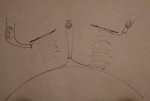
image_253715.jpg Would this setup make senses?

I don't get how a low power and high power coil setup would work otherwise. Is the highpower coil just packing more juice with the second inline coil?
 

Pusher

Lieutenant
Joined
Sep 2, 2014
Messages
1,273
image_253720.jpg

Sorry ladies and gentleman. I didn't picture things from the top. I had to mirror some things. Now it doesn't make sense again.
 

km1125

Chief Petty Officer
Joined
Aug 10, 2016
Messages
497

The yellow wires continued to be brittle the full length into the case (as well as corroded). You have to love how a manufacturer will make something that could last a hundred years, then add a wire that will make it 30. The red, blue, and black wires are still pliable and valid. The yellow ones are just trash.

I'm guessing that all those wires have a similar jacketing to them. The difference is that the yellow wires are running higher current continuously and therefore a MUCH higher temperature than those other three wires. The high temperature causes the jacketing to fail earlier and cause the copper inside to corrode quicker (which btw, then increases the temperature further!).
 

Pusher

Lieutenant
Joined
Sep 2, 2014
Messages
1,273
I guess that makes sense. Seems like spark plug leads do alright under similar situations though they are much larger.


Would a wiring setup like in post 53 allow the current from the first post to energize the second post to make it the hi speed coil? Seems like it's wrong since CDI says the red lead is the high speed.
 

Pusher

Lieutenant
Joined
Sep 2, 2014
Messages
1,273
The third paragraph of the below is making things clearer for me. Upon inspection of the high and low speedcoilsI see that one has about twice as many wraps which would explain the big difference in ohm testing and how the high low speeds are stepped down. I need an electronics for dummies course šŸ˜ž
 

km1125

Chief Petty Officer
Joined
Aug 10, 2016
Messages
497
I guess that makes sense. Seems like spark plug leads do alright under similar situations though they are much larger.
Spark plug wires have VERY little current in them, and only for a very small fraction of a second. They don't heat up at all from the power running through them, only because they are connected to a hot spark plug. Run 10 amps though a 20GA wire for a while and see how hot it gets... then wrap it in insulation so it can't cool itself and measure the temp again.

Would a wiring setup like in post 53 allow the current from the first post to energize the second post to make it the hi speed coil? Seems like it's wrong since CDI says the red lead is the high speed.

Wish I knew what the function for those other two coils were. It would seem to me (and just a wild guess) that the black would be the center wire and the blue one end and the red the other.. but that is completely a guess. If you've actually found it was wired the way the diagram was, go with that. As for which way they are wound, it would also help to know what they are for. Winding one way creates a positive voltage spike when the "N" magnet pole passes...winding the other way creates a negative spike when the "N" magnet pole passes. When the "S" pole passes, it reverses. That's why you have diodes in the charging system... so that all of those pulses become positive pulses. For the CDI it's different on how it's used, but the function is the same, so to answer your question, then "YES" you can energize any of the three leads with the way your diagram is displayed.
 

Pusher

Lieutenant
Joined
Sep 2, 2014
Messages
1,273
$44 of copper is on the way. In the meantime ....


image_253827.jpg

KM1125, Do you have any suggestions on a robust electrical wire for the stator leads? I'm thinking about going up a size also.
 

gm280

Supreme Mariner
Joined
Jun 26, 2011
Messages
14,597
I see this is move forward. I am watching it for sure. I have to admit, I would probably be doing the same thing faced with your option. I always thought that a burnt out stator and coils would be a challenge to repair this way. I mean the only materials are the core and wire. I have repaired seriously burnt circuit boards before and was even certified to repair circuit boards that were burnt all the way through. :thumb:
 
Top