


modopopcorn
Seaman Apprentice
- Joined
- Jan 18, 2013
- Messages
- 46
Hi guys! My last outboard was beyond salvation so I bought a new project to invest all my hard earned money into.
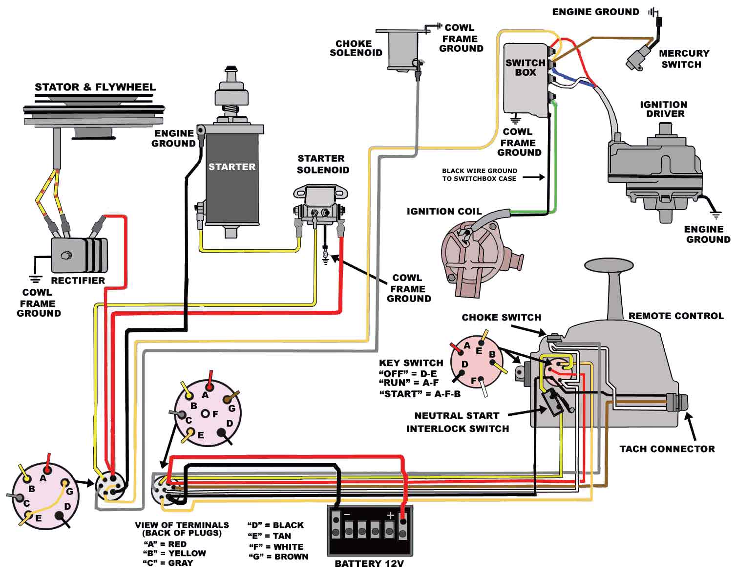
It's an 1970 Mercury Thunderbolt 500 in pretty good condition apart from the issue with stalling when shift into gear. Hopefully this has been sorted out as I cleaned out the carburetors today and the jets was almost clogged shut.
However, this is an 500M model, i.e. it didn't come with an electric starter from the factory, the previous owner bought this outboard with a boat in 2003 and retrofitted an electric starter on it, but when I went to pick the motor up earlier this week al the wiring was disconnected and the gentlemen I bought the motor from couldn't remember exactly how it's supposed to be wired correctly as it's a couple of years since it was unmounted from his boat and his memory was failing (poor old man).
The wiring loom came with four larger wires where I suppose the long red and black wires are supposed to be connected to the battery, however I can't really make out where the yellow/black and short black is supposed to go. Also there's another black large wire connected to the rightmost post on the starter solenoid.
All this is connected on a second solenoid that's connected to a wireless receiver that makes it possible to start the motor without actually being next to it (worthless feature I know but still kinda cool).
I really need help sorting out how to connect all this wiring and would greatly appreciate any help and advice I get.


")