MerControl tachometer setup

clueless75

Petty Officer 2nd Class
Joined
Jan 30, 2015
Messages
102
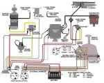
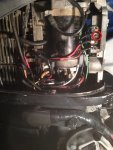
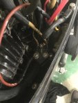
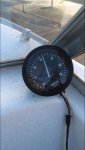
Hi everyone, I have a teleflex tach that connects to the MerControl box via tach harness, but i cant get it to work. The gauge reads about 400 RPM when not plugged in, then when plugged in (and engine running) it drops to 0. Can someone tell me how to hook it up properly? The motor is a 1971 Merc 800. I've tried switching around the wires and such but to no avail. I've opened the control box and theres no problem in there. The wires from the stator to rectifier are a tad bit corroded and may be frayed, so im thinking that could be a problem. Any help would be greatly appreciated, thanks guys.
 

Attachments

  • IMG_3041.JPG
    IMG_3041.JPG
    373.1 KB · Views: 4

GA_Boater

Honorary Moderator Emeritus
Joined
May 24, 2011
Messages
49,038
You can eliminate the wiring from the motor through the remote control. Get 3 pieces of wire and some alligator clips.
  • Remove the tach from the dash. If you have long wires and can see the back of the tach and can ID the pins, leave the tach in the dash. Never mind - I see you have the tach out.
  • Hook up one wire to the tach ground and ground on the motor.
  • One wire from +12 volts on the motor and the IGN on the tach.
  • Connect final wire from the SEND pin on the tach to one of the the two stator leads to the regulator.
  • Fire the motor up and see if the tach works properly.

If it works, the problem is in the harness. remote control wiring or the harness from the control to the tach. With these old Mercs, the internal motor harness, boatside harness and wiring inside the control box start to crumble with age.

Hope this helps.
 
Last edited:

GA_Boater

Honorary Moderator Emeritus
Joined
May 24, 2011
Messages
49,038
I just noticed on your pic of the back of the tach - The selector switch should be on 6P. It's set to 2P/4C, which is for a 4 cylinder 4 stroke.

Rotate the switch clockwise to 6P, don't try counterclockwise.
 

clueless75

Petty Officer 2nd Class
Joined
Jan 30, 2015
Messages
102
Ah I was wondering what that thing was for! Although when I tested the tach, I moved that switch to each position without any results...
 

clueless75

Petty Officer 2nd Class
Joined
Jan 30, 2015
Messages
102
Anyone know if I hooked up the wires correctly? Im not 100% that the brown/salmon wire is the send wire, or if the white wire is the ignition.
 

Silvertip

Supreme Mariner
Joined
Sep 22, 2003
Messages
28,762
If your boat has any other gauges, you can determine +12 volts and ground from the labels on the back of the gauge. Every gauge has has an "I" (ignition/12V) terminal that is hot when the key is on. The ground symbol on the gauge is ground. All you need to locate is the TACH signal wire in the harness which is probably gray.
 

clueless75

Petty Officer 2nd Class
Joined
Jan 30, 2015
Messages
102
I have no other gauges, and the tach wire harness (shown in original pic) plugs into the control box, which gathers all wires into a thicker wire which I can't access without cutting it open (which in not going to do unless absolutely necessary). I do know that the tach signal comes from the rectifier, and the rectifier also leads to charging the battery. I haven't even checked if the motor charges the battery, but if it does do I assume that the tach should be getting a signal? If the motor doesn't charge the battery, should I be checking my rectifier/stator/wires from stator?
 

GA_Boater

Honorary Moderator Emeritus
Joined
May 24, 2011
Messages
49,038
White is IGN or +12, black is ground and tan/brown is SENDer wire from the rectifier. At some point in time Merc changed the wire colors, but back in 1971 the wiring matched the colors in the first sentence.

So yes, you are connected properly at the tach.
 

Silvertip

Supreme Mariner
Joined
Sep 22, 2003
Messages
28,762
Don't be surprised if your tach is toast since you've indicated you have been swapping wires around. I have no idea if your tach is polarity protected but reversing polarity on any electronic device is a risky move. Tachometers are normally capacitor coupled on the sense line so 12 volts on the send line would probably not damage anything but then there is always "Murphy's Law" to contend with. An easy way to check if the charging system is working is to measure the voltage at the battery with the engine off. Note that reading. Start the engine and rev it to about 1500 - 2000 rpm and measure battery voltage again. If it is the same or lower than the first reading the battery is not being charged. If the voltage is higher (13.5 - 14.5 volts) the system is working. If you don't have a hand held multi-meter (volt, ohm, milliammeter) you need one. Trot over to Lowes, Home Depot, Ace or any store that sells electrical stuff. The meter can be had for about $10 - $15.00 and up.
 

clueless75

Petty Officer 2nd Class
Joined
Jan 30, 2015
Messages
102
Alright, but then again, how do I know I'm getting 1500-2000 RPMs when I don't have a tach? Haha, I'm just kidding, I can just listen and guess. Thanks for the tip, I'll try it out either today or tomorrow :)
 

clueless75

Petty Officer 2nd Class
Joined
Jan 30, 2015
Messages
102
No Title

UPDATE: It works!! After finding a wiring diagram (see pic 1 below), I realized the previous owner had hooked up the tach signal wire to the switchbox (see pic 2 below) on a terminal that is not supposed to be hooked up to anything according to the diagram. So once I hooked up the wire to that stator wire on the rectifier (see pic 3) and started up the motor, the tach worked! (see pic 4) Also, I checked the battery voltage with an electronic multi-meter without the motor running and it read something like 12.74V but when the motor was running, it read 0 or -0... However I also used an analog multi-meter which read some number (I cant remember or read it), then with the motor running, that number fluctuated a bit above that number which makes me think that it is charging, so thats good. Thanks everyone for all the help!
 

Attachments

  • photo238266.JPG
    photo238266.JPG
    49.8 KB · Views: 5
  • photo238267.JPG
    photo238267.JPG
    143 KB · Views: 4
  • photo238268.jpg
    photo238268.jpg
    107.3 KB · Views: 4
  • photo238269.jpg
    photo238269.jpg
    47.4 KB · Views: 5
Top