Re: Is electronic conversion a simple drop in?
So the wire itself is the resistor?
Yes!
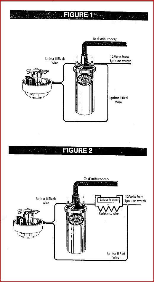
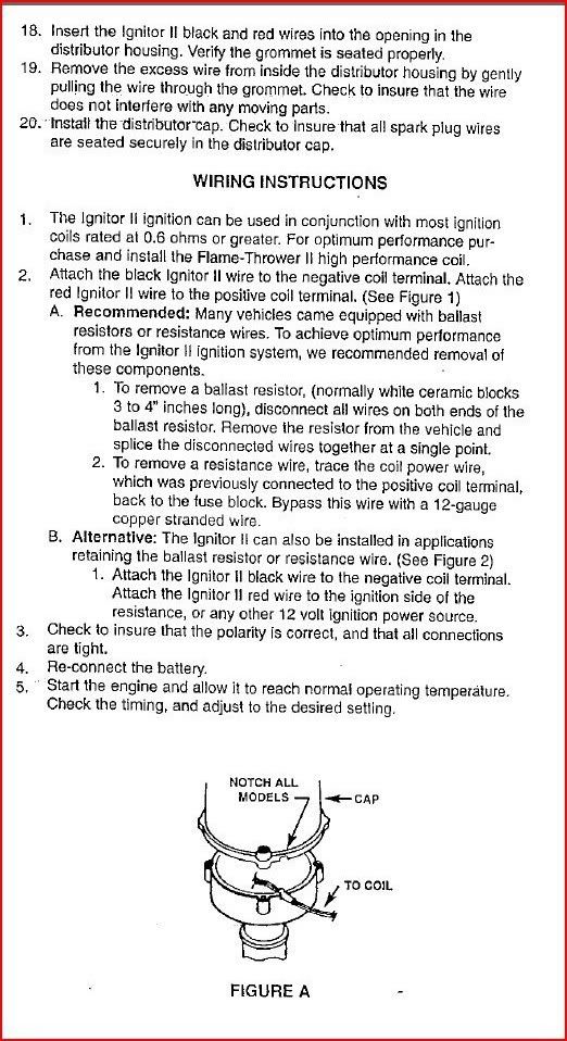
The instructions that came with the unit have 3 diagrams and the one with the resistor and elec. module shows the red lead from the electronic module going to the incoming side of the resistor (shown as a box in the diagram) so that's why I thought the resistor was an actual unit, not the wire itself. This also lead me to think that the ignitor module needs 12V, not the coil.
They both need 12volts, so just put the red wire on the (Plus+) side of the coil, Along with a 12volt switched (ign key) non resistor wire, and the starter wire (it should be 3 wires total)
So, if my COIL needs an external resistor and I run full 12V to it, it won't get cooked? Or is the resisance just in place so the points don't get cooked? For testing purposes, I can remove the wires from the + side of the coil and use my elec. tester to see which wire is which, correct? I don't want to connect the battery if I have things wired wrong and risk burning somethig up.
I appreciater your patience!
Forget about the resistor, unless your Ignitor instructions call for one. The resistor is only there to keep your points from getting cooked, thats the only reason you have that "Warning on the coil!", thats all it is, a warning not to use points without a resistor,,, Your coil will be fine to use as is, it does not need a resistor.
Many years ago cars used to have a little white ceramic ballast resistor, it's almost obsolete, it's all in the wiring now.
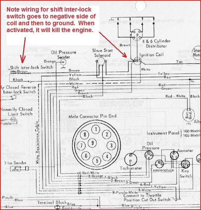
Yes, use your elec. meter on the wires on the Plus + side of the coil, one should be a full 12volts when cranking, and prob dead all other times, The other should be the resistor wire (ignition) and read around 6 volts or less.
Somewhere in here, there Might be the shift interrupt wires?
The other side of the coil, will feed the Dizzy, and the Tach, once you put 12volts to the Plus + side of the coil.


 and a purple/yellow wire which runs to the starter motor and only cranks 12V upon starting. Back to the brown wire, it reads 10.52V with the ignition switch on. I cannot find a full 12V switched wire anywhere!!! The purple wire going to the choke also reads 10.52V. So, is 10.52V as good as it gets?