


- Joined
- Jul 18, 2011
- Messages
- 17,732
Greetings-
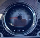
I have been trying to select the speed input source to be the GPS on my SC1000 Speedometer. The User Manual makes it sound simple (hold - Mode and + buttons for 6 seconds, blah, blah, blah)
All the thing wants to do is go into the depth gauge menu, no matter what I do.
Any experts among us who can assist ? I get GPS speed on the VesselView display, but would also like the speedometer to do the same.
I’m not sure what the input source is currently for the speedometer - if I happen to get to a GPS screen is says ”NO DATA “
I hate these gauges


 . . . I did find a wiring diagram in the MG3000 manual that is making some sense. (The manual does not appear to be copyrighted).