In any case, I took readings with my home made DVA and it works great.. Thank you TexasMark.
I'm getting around 53-54 volts at the green/white wire at all three coils while jumping battery voltage to the connection on the starter solenoid that has the yellow/red wire (ignition). Motor cranks over fast. I have zero spark at all three spark plugs. (using both a spark gap check tool and a spark plug to a ground)
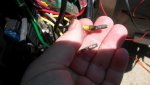
I went to disconnect the two yellow wires / bullet connections they were tucked in behind and I did not notice before..... the insulation near the bullet was "burned"!!!!.... and some corrosion was seen on some areas of the bullets. Looks like I should find some 12 gauge wire.... and solder in some new sections with shrink tube.
I'm somewhat at a loss at this point because between the CDI information I looked up for the 3 cylinder motors, and the seloc manual... I don't know which set of measurements really apply to my engine. So I don't know if the 54 vdc is adequate. The CDI chart talks about measuring a blue wire to engine ground, it doesn't say where to take the measurement... i.e. close to the switch box? with the circuit disconnected at a bullet juncture? and it talks about a power pack... where is this power pack? Is this the switch box?
It would be a strange coincidence that that all three ignition coils would go bad at the same time, so I'm thinking maybe the voltage is supposed to be more like 150vdc, but that is a guess (I don't like guessing). Is a mercury manual a better option? I'm not liking the Seloc nor CDI manual, but maybe after I can learn some items between the lines it will make more sense.
After disconnecting the yellow wires (stator to regulator) I did again confirm "no spark" on all three cylinders per the CDI instructions, I tested the reading at the coils again as well, all around the same voltage as before.
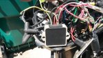
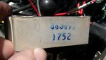
Now I was looking in the seloc manual and trying to find the correct pin-out for the regulator/rectifier and there is nothing in the book that matches... there are no A,B,C labels on the wires coming out of my regulator. Can anyone give me a hint on how to test the regulator? mine has a grey wire for the tack, black-ground, two red wires (one to fuse, one to solenoid connection) and two yellow wires (stator).
I can tell already the the resistance reading fluctuates when I move one of the yellow wires coming out of it... so there must be some heat damage to the wire. I can potentially cut off enough of it to repair it but I'd like to confirm the device itself is ok to use, I'm leaning towards replacing it.
I will post a picture in case any of you guys have any pin-out or test information.... resistance from yellow to red, or to the black ground... I don't know if this is an original mercury part or an aftermarket part (bought the boat used). None of the wires are showing a dead short to ground, but I'm getting wildly different resistance readings in the k oms or mega ohms depending on which circuit.
Thanks in advance for any info..