Battery not charging - rectifier OK

AAusbro51

Cadet
Joined
Mar 1, 2017
Messages
18
I apologize if this is already covered in a past post, but the topics/problems/resolutions I'm seeing surround the rectifier NOT working. Here's what I'm experiencing::

Motor: 1978 Johnson 85ML78C
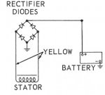
This past May, my battery was not re-charging while I was running around on the water. After doing some homework, I zero'ed in on the rectifier. Removed it and tested the diodes. 3 of the 4 were dead. Ordered a replacement. Tested the diodes upon arrival - everything looked super. Installed it and tested it with the motor running. The battery was receiving 12.6v to 14v. All good.

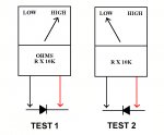
Since then, I've been out a dozen times or so. Everything was working & charging fine - except for yesterday. The starter batt voltage dropped all day, winding up to be around 10v at the end of the day. I don't run anything on that battery, other than the depth finder and the radio. The depth finder displays the battery voltage. When the motor ran on previous trips, it would show 13v+ indicating that the starter batt was charging. Yesterday it never perked up as we motored around. I suspected the rectifier had failed - however upon removal and inspection, all 4 diodes test at about 400 (which from what I'm seeing on youtube/internet, indicates a good rectifier).

I also confirmed the battery voltage with an actual volt meter to make sure the depth finder wasn't giving me a false reading.

So.... if the 4 rectifier diodes are testing "good", what else would cause a working charging system to suddenly stop?
 

gm280

Supreme Mariner
Joined
Jun 26, 2011
Messages
14,601
Okay not sure what the 400 means. If you own a multi-meter, does it have a diode function capability? If so, test the rectifier via that setting to verify the diodes are good. And it they do read good, what does you stator resistance read? If the stator has a broken wire or wires, or shorted out, you will not be charging any battery. So a little more testing yet to locate the problem. You r stator wiring should have some resistance and not any resistance to ground. In other words, if you read anything from any one of the wires coming from the stator to ground, the stator is bad. But remove all the wires from the rectifier to test them to ground. JMHO
 

oldboat1

Fleet Admiral
Joined
Apr 3, 2002
Messages
9,612
^^agree. Any "event" that might have affected the rectifier? (disconnect while running, reversed polarity at any point, ....)
 

F_R

Supreme Mariner
Joined
Jul 7, 2006
Messages
28,195
No Title

I don't know what 400 means either. When it comes to testing rectifiers, I lay the new-fangled multimeters aside and get out the old fashioned analog meter. Or even a simple continuity test light.

Then test each diode in both directions. Each one should show continuity in one direction only. That's 8 tests on a four-diode rectifier. If it fails any one of the 8 tests, it is kaput.
 

Attachments

  • photo61331.jpg
    photo61331.jpg
    25.5 KB · Views: 0
  • photo272123.jpg
    photo272123.jpg
    46.3 KB · Views: 0
Last edited:

AAusbro51

Cadet
Joined
Mar 1, 2017
Messages
18
Thanks for the replies!

Sorry- I was trying to be general on the results of my rectifier testing.
The 400's meant that I was seeing .4## in the four test directions that needed to see activity. The other 4 directions were 0.000. I concluded that the rectifier was a-okay.

I am not aware of any "event" that has occurred since last being on the water. I did replace the starter battery with a newer one before this most recent trip (same style as the original).

I'm not familiar on how to test a stator. No broken wires on initial inspection. The posts are a tick dirty, but again, it was working before yesterday.
I'll do some looking up on how to test the stator.
 

Joe Reeves

Supreme Mariner
Joined
Feb 24, 2002
Messages
13,262
Keeping it simple.... no numbered specific readings required.... test that 3 wire rectifier as follows:

********************
(Small Rectifier Test)
(J. Reeves)

Remove the rectifier wires from the terminal block. Using a ohm meter, connect the black lead of the ohm meter to the rectifier base (ground), then one by one, connect the red lead of the ohm meter to the yellow, yellow/gray, then the red wire (some rectifiers may also have a fourth yellow/blue wire. If so connect to that also). Now, reverse the ohm meter leads and check those same wires again. You should get a reading in one direction, and none at all in the other direction.

Now, connect the black lead of the ohm meter to the red wire. One by one, connect the red lead of the ohm meter to the yellow, yellow/gray, and if present, the yellow/blue wire. Then reverse the leads, checking the wires again. Once more, you should get a reading in one direction and none in the other.

Note that the reading obtained from the red rectifier wire will be lower then what is obtained from the other wires.

Any deviation from the "Reading", "No Reading" as above indicates a faulty rectifier. Note that a rectifier will not tolerate reverse polarity. Simply touching the battery with the cables in the reverse order or hooking up a battery charger backwards will blow the diodes in the rectifier assy immediately.
 

AAusbro51

Cadet
Joined
Mar 1, 2017
Messages
18
Thanks Joe-

Sounds much like what I did. Just for fun, here's what I'm seeing on the rectifier:

Multi-meter dial is in the diode mode-
Blk lead to base - red lead to gray/yellow: 0
Blk lead to base - red lead to yellow: 0
Blk lead to base - red lead to red: 0
Red lead to base - blk lead to gray/yellow: .484
Red lead to base - blk lead to yellow: .485
Red lead to base - blk lead to red: .933
Sorry for the misinformation earlier. There isn't 8 tests... there's 6.

** if the red wire should be reading lower - but it's reading higher - would that mean that the rectifier is actually bad??
 
Last edited:

F_R

Supreme Mariner
Joined
Jul 7, 2006
Messages
28,195
You are not doing what I said to do. I said to do two tests on each of the four diodes.

1. Connect meter leads to base and yellow. Get a high or low reading
2. Reverse the meter leads to the same points. If you got a high before, you should get a low now and vice-versa
Tests 1 and 2 covers one of the four diodes

3 and 4---do the exact same thing between the base and the other yellow (yellow/grey)
Tests 3 and 4 covers the second of four diodes

5 and 6---do the same exact thing between the red lead and one of the yellows
Tests 5 and 6 covers the third of four diodes

7 and 8---do the exact same thing between the red and the other yellow (yellow/grey)
Tests 7 and 8 covers the fourth of four diodes

Testing between red and base is totally unnecessary, but you can do it if you want to--I don't care. If it passes all 8 of the above, it will pass between red and base.
 

AAusbro51

Cadet
Joined
Mar 1, 2017
Messages
18
Sorry - I'm trying, F_R.. I really am. Here's what I'm seeing trying your test:

First # is with black lead on base / second is reversed
Base & yellow: 0 / .484

First # is black lead on base
Base & yellow/gray: 0 / .482

First # is black lead on red wire
red & yellow: 0 / 0

First # is black lead on red
red & yellow/gray .485 / 0
 

F_R

Supreme Mariner
Joined
Jul 7, 2006
Messages
28,195
So it failed with the 0/0 result.
A couple of "events" that will kill a rectifier in a nano-second:
Reversing battery polarity (duh)
Disconnecting the battery while running
Loose battery cables
Using a high Amp battery charger with motor's battery cables still connected.
And the biggie--corroded battery cable connections. Remove them and clean them shiny bright with sandpaper or wire brush.
 

jakedaawg

Rear Admiral
Joined
Jun 26, 2012
Messages
4,275
I might add that if the cables appear to be original or even from the 90's, replace them. Wire does not last forever on the water.
 
Top