1996 Four Winns Sundowner with 5.0 Cobra engine and drive

Lpgc

Petty Officer 2nd Class
Joined
Jun 17, 2023
Messages
164
Can’t say, I’d ask on www.ifourwinns.com
I’m sure someone has dealt with it….

Seems there's no way I can create an account on that forum. In June last year I tried to make an account, there was no 'create an account' option but the FAQ's pointed me to email an administrator, I sent an email but they didn't reply. Maybe they banned none US users from creating an account..?

Pasted from their FAQ's -
Why can’t I register?
It is possible the website owner has banned your IP address or disallowed the username you are attempting to register. The website owner could have also disabled registration to prevent new visitors from signing up. Contact a board administrator for assistance.
 

Lou C

Supreme Mariner
Joined
Nov 10, 2002
Messages
12,025
That’s odd but that site is pretty inactive, maybe no one is monitoring it regularly. I’d try searching posts on that all in one gauge design then. It was a lousy idea that a lot of people had trouble with and IIRC there was a company making custom panels to replace that panel into which you could install custom gauges of your choice. Might do a search for custom gauge panels & see what comes up.
 

Lpgc

Petty Officer 2nd Class
Joined
Jun 17, 2023
Messages
164
I found this thread which mentions a couple of companies https://www.smwebhead.com/phpBB3/viewtopic.php?f=21&t=13428&p=162347&hilit=gauges#p162347

This post answers my question about whether or not the car style cluster gauges use standard sensors...
"All the wires in the back come from standard sensors that will work with standard gauges, you'll just have to keep track and label them all and hook them up to the new gauges. You'll also have to build some kind of panel to hold the gauges. Not a big deal, people do it here all the time I'm sure someone will post up their conversion. Faria makes a nice gauge kit. I used it. Like it."

Still slow progress on the boat. The little electric fuel pump arrived late yesterday, it does pump fuel out of the boat tank but very slowly. After pumping another couple of pints of fuel out the rest of the fuel looked OK, no milky colour or water settling at the bottom of the glass jug, so I used the contaminated fuel I pumped out earlier to help burn a tree that fell over last year (lit it using burning paper on the end of a long pole) lol. Took around an hour to pumped just 6 gallons out of the boat into the car but it doesn't really matter how long it takes because I can be doing other things while its pumping.

A 12mm x 2mm flat screwdriver bit I ordered arrived yesterday, I was able to open the SX drive leg drain plug, the fluid looks clear and blue with no sign of water in it so I'm happy about that. Is Volvo Penta own brand drive fluid blue?
 

Lou C

Supreme Mariner
Joined
Nov 10, 2002
Messages
12,025
Not sure but I know that the Mercruiser High Performsnce gear lube is that color….
 

kenny nunez

Captain
Joined
Jun 20, 2017
Messages
3,105
At this point I suggest pulling the suction tube out of the tank. Inside the tube there is a very fine screen that plugs up often, remove and throw it away.
 

Lpgc

Petty Officer 2nd Class
Joined
Jun 17, 2023
Messages
164
At this point I suggest pulling the suction tube out of the tank. Inside the tube there is a very fine screen that plugs up often, remove and throw it away.

Thanks.

I didn't manage to get more than maybe a gallon out of the boat tank using the little electric pump today, the pump was still running but the flow completely stopped with the boat tank still half full. I wondered if it was broken or needed a bigger head than the half tank of fuel remaining in the boat but it's supposed to be self priming.

It does seem likely the screen is plugged. Is the screen in the pickup tube inside the tank?

I removed the level sender again to measure effective tank depth for a new level sender (bottom inside to top outside), it measures 240mm. I looked at the options for a new sender (needed to be a 240>33Ohm and close to but not deeper than 240mm, delivery dates, cost) and bought a 225mm up/down type (as opposed to float arm type) https://www.ebay.co.uk/itm/386817027161?var=654074592945
 
Last edited:

kenny nunez

Captain
Joined
Jun 20, 2017
Messages
3,105
Yes, the screen is inside the tube. Also if you are trying to draw fuel through the anti siphon valve that is mounted on the pickup elbow then, that is why the pump cannot draw the fuel. Just drop the suction hose of the pump in the fuel sender hole.
 

Lpgc

Petty Officer 2nd Class
Joined
Jun 17, 2023
Messages
164
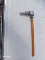
This is a picture of the pickup tube, doesn't seem there's a filter/screen inside it.

20240512_151447.jpg

I think the problem is the pump not being able to suck uphill. It will self prime to some small extent but the flow rate is so slow that teh fuel just trickles slowly from the output pipe, if the output pipe isn't full of fuel it kind of loses the siphon advantage and sees only the lift height to the pump itself.

I think I've already pumped out any fuel containing water from the boat tank, so I don't think there'd be much of a problem using the fuel in the boat tank to fuel the boat now (and my car runs fine on the fuel I removed from the boat tank). But I'd still like to pump the rest of the fuel out of the boat tank... Its octane rating must be lower than fresh fuel.

I bought a hand transfer / syphon pump that comes with a dipstick adapter to remove old engine oil via the dipstick tube. Plan is to connect the hand transfer / syphon pump in series with the electric pump and have the electric pump lower down (to keep its prime), then see if it will pump the fuel out of the boat tank. If not the transfer / syphon pump may prove useful when changing the boat engine oil.
 

Lou C

Supreme Mariner
Joined
Nov 10, 2002
Messages
12,025
Did you check the anti siphon valve? That’s the barbed fitting that is screwed into the square piece. They have a ball & spring inside that keeps gas from flooded ins into the bilge if the fuel hose between the tank & pump leaks….
My boat had that problem like 20 years ago when we first bought it….
If they get corroded or jammed with crud it will reduce the fuel flow to the point where the engine will start & run but won’t plane the boat. My mechanic replaced the cheap aluminum one with a better quality one Evinrude/Johnson brand.
 

Lpgc

Petty Officer 2nd Class
Joined
Jun 17, 2023
Messages
164
Did you check the anti siphon valve? That’s the barbed fitting that is screwed into the square piece. They have a ball & spring inside that keeps gas from flooded ins into the bilge if the fuel hose between the tank & pump leaks….
My boat had that problem like 20 years ago when we first bought it….
If they get corroded or jammed with crud it will reduce the fuel flow to the point where the engine will start & run but won’t plane the boat. My mechanic replaced the cheap aluminum one with a better quality one Evinrude/Johnson brand.

I tried sucking on the barb, it did seem to allow me to suck air through without much resistance.
 

Scott06

Vice Admiral
Joined
Apr 20, 2014
Messages
5,791
I found this thread which mentions a couple of companies https://www.smwebhead.com/phpBB3/viewtopic.php?f=21&t=13428&p=162347&hilit=gauges#p162347

This post answers my question about whether or not the car style cluster gauges use standard sensors...
"All the wires in the back come from standard sensors that will work with standard gauges, you'll just have to keep track and label them all and hook them up to the new gauges. You'll also have to build some kind of panel to hold the gauges. Not a big deal, people do it here all the time I'm sure someone will post up their conversion. Faria makes a nice gauge kit. I used it. Like it."

Still slow progress on the boat. The little electric fuel pump arrived late yesterday, it does pump fuel out of the boat tank but very slowly. After pumping another couple of pints of fuel out the rest of the fuel looked OK, no milky colour or water settling at the bottom of the glass jug, so I used the contaminated fuel I pumped out earlier to help burn a tree that fell over last year (lit it using burning paper on the end of a long pole) lol. Took around an hour to pumped just 6 gallons out of the boat into the car but it doesn't really matter how long it takes because I can be doing other things while its pumping.

A 12mm x 2mm flat screwdriver bit I ordered arrived yesterday, I was able to open the SX drive leg drain plug, the fluid looks clear and blue with no sign of water in it so I'm happy about that. Is Volvo Penta own brand drive fluid blue?
Re gear lube - I believe VP lube is clearish brown. Likely someone put merc hi perf lube in there. I do recall someone saying they had cone clutch slipping issues with Merc lube in VP drives but not sure how accurate that is
 

Lpgc

Petty Officer 2nd Class
Joined
Jun 17, 2023
Messages
164
Today I flushed the fuel pump, fuel filter / water separator, metal fuel pipes and carb float bowl with fresh fuel, then fitted them. Flushed the carb by connecting the steel fuel pipe with a rubber hose and funnel filled with fuel attached, then repeatedly opened the throttle to run the fresh fuel out via its accelerator pump.

I have a carb rebuild kit on order but I hope the boat is ready for testing before the rebuild kit arrives (could be a couple of weeks as its coming from your side of the pond) and to test the boat with the carb as it is (before rebuilding)... Seems no leaks from the float bowl etc in my testing today so I'm hoping the carb will work adequately for a test on the river.

Had some problems with spark plugs. Last year I didn't struggle much to remove or refit spark plugs but I forgot how I did it and don't have all the same tools now (same depth 5/8 hex plug socket with hex head at the extension end, same 1/4 to 3/8 adapter, etc). Also last year I bought some Champion RV15YC4 plugs. Started fitting those plugs but broke some due to putting side forces on the ceramic parts due to problems with the tools I was using. Then noticed the build quality of those plugs seemed dire so I suspected they were fake / none Champion. My usual trusted plug sellers don't sell those plugs so I thought I'd switch to an NGK alternative. Ebay sellers (including a trusted source) were listing NGK BPR4FS as alternative/compatible with Champion RV15YC4 so I bought 12 of those plugs (thinking I'd probably break a few trying to fit them) and did fit them without breaking any... But I noticed the BPR4FS tips don't protrude as much as the RV15YC4 into the cylinder and the ceramic bit is also a bit shorter. So I phoned a local engine builder that builds a lot of American engines including SBF's, they told me they'd never use BPR4FS because it has the wrong heat range but they often use NGK BPR6FS or BPR7FS. I now have a set of NGK BPR6FS plugs on order from a trusted source and will swap them in when they arrive using the new tools I ordered to do it :rolleyes:. Hopefully if/when I've fitted them I won't have a problem fitting the new plug leads... I managed to get most of them on with a secure clip but there are a couple of leads I couldn't be 100% sure were clipped on properly with the BPR4FS that I have in at the moment.

The new fuel level sensor should be arriving soon. When it's here I plan on disconnecting the positive connections to the coil (feed power and wire to the electronic ignition in the distributor) and testing the gauges on the dash. I have some 1 watt resistors on order which I'll place in series with sensor wiring such as fuel gauge, coolant temp gauge, oil pressure gauge to see if those gauges point where they should over the range of resistances I apply.

Questions...

I believe I can run the engine i the yard if I connect a water supply via a hose to the raw water input on the thermostat. Does it matter if the drive leg is fitted for this?

Do I need to be concerned about bleeding the engine coolant channels of air? I ask this because I can see that water can enter the engine by flowing in through the hose that enters the water pump from the thermostat housing but with the thermostat closed I don't see how it would bleed the air out... if water can enter at one end but the other end is closed it seems there is potential for airlocks in the engine? The old thermostat had a V cut into it's outer edge, the new thermostat doesn't so could completely seal.
 

Lou C

Supreme Mariner
Joined
Nov 10, 2002
Messages
12,025
What I'd do....
if your raw water pump runs off a belt, disconnect the belt, this way you won't burn up the impeller
As far as bleeding out air, what I have done in the past to ensure there are no or minimal air pockets...
Disconnect the large hose that goes from the front circulating pump to the stat housing, at the thermostat housing, and fill the block with water via this hose. When the water spurts out of the thermostat neck, the block and heads are full. Reconnect the hose. Then I like to fill each exhaust manifold with water via the feed hoses that connect to the 'stat housing. Reconnect the hoses and you can run the engine with a water hose hooked up to the raw water intake fitting on the stat housing. It doesn't matter if the outdrive is on or not, because you have no impeller in the drive like on the dog clutch Cobras do. While most will say the engine will self fill with water, that is true of the manifolds which get water right from the stat housing. The block will take longer to self fill and my way avoids any hot spots that can happen when the block is filling via the raw water hose.
The engine will fully be filled when the stat opens, but the stat doesn't open till hot water is up against the heat sensing pellet.
 

kenny nunez

Captain
Joined
Jun 20, 2017
Messages
3,105
Leave the drive off and connect the hose to the thermostat inlet. Do not worry about bleeding the cooling system. It is not like a closed system.
 

Lpgc

Petty Officer 2nd Class
Joined
Jun 17, 2023
Messages
164
The engine will fully be filled when the stat opens, but the stat doesn't open till hot water is up against the heat sensing pellet.

That was my concern.
Though I suppose every time the engine is stopped the water level inside it will fall and not rise again until the engine is run again and raw water pump runs? If that is true then if it doesn't self prime we'd need to worry about it priming every time we shut the engine off and restart it?

Not done much on the boat again today. just removed the spark plugs so I'll be ready to fit NGK BPR6FS plugs. The new plug leads are difficult to fit and remove, I might use the old leads when I put it together.

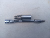
Fed up with difficult access to plugs, seemed it'd be a lot easier if I used a 5/8 or 16mm plug socket with 1/4 drive and universal joint adapter but 1/4 drive plug sockets are like hens teeth, so I made a 5/8 1/4drive plugs socket... Cut the drive end off a 5/8 plug socket, cut the socket end of a 11mm 1/4 drive socket short, welded them together. Just had to make sure it was as short as possible while still being long enough to work with whatever spark plugs I might use (and having the hole inside at the top to take the spark plug tip). I used a Champion plug to gauge the design as they're a bit longer than the NGKs.

20240515_185832.jpg

The swivel joint I used is a hex wobble joint (or read impact type CV joint), the wobble joint is more constant velocity than a normal universal joint but is also longer and wider. It works fine with the modified socket to remove and fit plugs in the confines of the marine exhuast manifold but I will be using a normal 1/4 universal joint in future instead of the wobble/impact joint and expect it will give more clearance.
 
Last edited:

Lou C

Supreme Mariner
Joined
Nov 10, 2002
Messages
12,025
The way the cooling system works with raw water cooling on an inboard is that the engine and manifolds stay pretty much full once it is primed. The exhaust elbows will drain some out but the water level with the engine off is probably above the level of the joint between the manifold and elbow. This is why you MUST drain the engine and exhaust any time you will have below freezing weather with a raw water cooled system.
The spark plugs, well you have my sympathies, I have heard the Fords are tough because of the design of the manifolds. The GM engines are very easy, I can do it in my sleep I've been doing it for so long. I think making a special socket is the only easier way. Yours is brilliant!
 

Lpgc

Petty Officer 2nd Class
Joined
Jun 17, 2023
Messages
164
I watched a YouTube video about changing Ford plugs made by Michael Romer, he used 2 different length plug sockets, the longer socket had a 3/4 hex at the drive end so he was able to put a spanner on it to slacken (or final tighten) plugs, the shorter socket he was able to use a 3/8 to 1/4 adapter with a 1/4 universal joint. That's the way I did it last year (before I watched his video) but I couldn't find my longer socket with the 3/4 hex, my short 3/8 to 1/4 adapter or my short 1/4 universal joint. Then it occurred to me I could make a socket just the right length and if native 1/4 drive (so no need to use a 3/8 to 1/4 adapter) there would be enough clearance to use most 1/4 universal joints, no need to use multiple sockets or a spanner. The longer socket with 3/4 hex to use a spanner on works OKish if the hex is in the right position but it can be a struggle or impossible to get a spanner on if it's in the wrong position because the manifold is in the way. I seem to remember grinding down a 3/4 spanner to slacken one or two plugs using the longer socket, then switching to the shorter socket. With my modified socket the angle of the Ujoint is much straighter than using Michael's setup with the 3/8 to 1/4 adapter.

I would've thought the engine coolant would drain to sea level with the raw water pump not running?
 
Last edited:

Scott Danforth

Grumpy Vintage Moderator still playing with boats
Staff member
Joined
Jul 23, 2011
Messages
47,872
nope, motor is designed like a p-trap. water will drain to the top of the thermostat housing at best unless you pull the block drains
 

Lpgc

Petty Officer 2nd Class
Joined
Jun 17, 2023
Messages
164
nope, motor is designed like a p-trap. water will drain to the top of the thermostat housing at best unless you pull the block drains

Ahh yes I see that now. Earlier I made the mistake of thinking the lower pipe from the water pump (which connects to the thermostat housing) was connected lower to the raw water pump.

I decided to use the new BPR4FS plugs I already have so I put them back in. It was much easier using the socket I adapted even though I'm still using the 1/4 impact universal joint instead of finding/buying a normal (shorter narrower) 1/4 normal universal joint.

Refitted the old plug leads, they go on much easier than the new.

Test fitted the new V belts, they all fit OK. Removed the raw water pump belt again.

Disconnected the positives from the coil. Connected a battery to the port side battery connectors and tried to crank the engine, the starter tried to crank the engine but clicked on/off as though the battery were flat. Tested the battery, it had good charge at 12.8V which made me worried I hadn't fitted the starter motor properly. Tried cranking again, smoke came from the port side negative battery cable near where it connects to the battery. I looked at the battery cable, someone has put tape around the area the cable was smoking from so I thought maybe someone tried to join wires under the tape... but still worried in case there was a problem with the starter motor (I know the engine turns OK by hand cranking). I didn't check under the tape but moved the battery to the starboard side battery connectors, switched the battery selector to the starboard side battery and tried cranking again, this time it cranked no problem :) ..so it seems I need to look under the tape on the port side battery earth wire. I only cranked it for a few revolutions but still have a concern.. At a certain position during cranking (say just where one of the cylinders would be on compression stroke) the cranking speed increased, could tell by the sound, so I'm hoping there isn't going to be a problem with compression on one cylinder, maybe it's just because a lifter needs to bleed etc. Any thoughts on this? If you disable the ignition on your boat / car and crank the engine does the cranking speed the same or is there a certain point (like for maybe compression on one cylinder) where cranking speed seems to increase?

The gauges (volts, temp, oil pressure, trim) do move with the ignition on. With ignition off they all point too far to the right, with ignition on they all point even further to the right and go off scale... It's as though the base reading for all the gauges has moved from pointing to the left to pointing somewhere in the middle, so maybe I can fix the gauges just by pulling the needles off and putting them back on in the correct position? If that is true I wonder if at some point someone has connected a battery the wrong way making the gauges point further to the left and moving the base position by moving the axes inside the needle pointers. A friend was here while I was testing the cranking and gauges, I had him move the part on the transom that goes up/down/steers, the trim gauge does move with the transom part but it starts in the middle and goes off scale to the right pointing way past the down position when the transom bit is pushed all the way down.

Seems I lost a couple of jubilee clips for the pipes that run from the thermostat housing to the exhaust manifolds but I think I have a pack of mixed jubilee clips, so next thing on my to-do list is find the pack of jubilee clips. I might even get around to priming the cooling system, reconnect the igniton wires at the coil and dizzy cap, fill the pas pump, make some adapter to connect the hosepipe to the thermostat housing and try to start the engine...
 

Lpgc

Petty Officer 2nd Class
Joined
Jun 17, 2023
Messages
164
Questions about oil level... The dipstick has hatching to show safe level, below the hatched area it reads 'fill' but I don't know where full level is. There are a couple or dots / holes higher on the dipstick. The level is reading between those dots, is that correct or is it overfilled? The problem is I put some oil in it to test the oil pump, I measured how much oil I put in but didn't realise I hadn't connected the oil pressure sensors pipe so quite a lot of the oil I put in squirted onto the floor without me knowing. It seems I then filled to between the 2 dots thinking that was correct but now I'm wondering if its very much overfilled...?

My dipstick runs from the port side of the engine, down underneath the oil pan and enters the oil pan on the starboard side half way up the oil pan. I don't remember much about the angle the dipstick enters the oil inside the pan, I don't know if there's a tube/guide that takes the dipstick to the bottom of the oil pan or if it just kind of points sideways. I suppose if it points sideways it'll either read empty or full but never inbetween. I cleaned the sump inside before refitting it but don't remember whether or not it had a tube running from the dipstick hole on the outside to the bottom of the inside.
 
Top