Coil Voltage

jeffnick

Senior Chief Petty Officer
Joined
May 24, 2004
Messages
695
NOTE: This thread was started by moving this post and a couple following from THIS THREAD to here.
Don S.


I now the OP doesn't have a points ignition but this needs to be cleared up. Even if he had a points system this would only be true if the points were closed. With the points open, you would measure 12V no matter if a ballast resistor was in there or not.

OK - I've learned that an electronic ignition can run a coil that requires ballast even without the ballast - and that makes sense. But doesn't my original statement still hold - a coil that requires ballast should not be run on 12 volts?

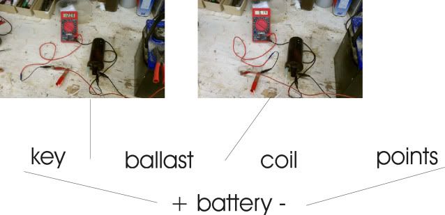
I admit, I didn't go to boat school or have any formal training on the subject, but I do mess with stuff a lot on the boat and on the bench. Here's how my boat is wired with a pic of the ballast and coil I took off, hooked up to a battery.

When I switch on the key, 12 volts goes to the ballast - whether the points are open or closed.
On the coil side of the ballast with the key on, I have about 6 volts. To me, this means that the coil is designed for +/-6 volts, not 12. While cranking, the ballast is bypassed because the starting current can pull the battery voltage down to 9 volts or less. So the coil still gets at least the 6 volts it needs to make spark.

I may not be thinking correctly, but if I take the ballast out of the picture, I'll be giving that '6 volt' coil 12 volts all the time and it's bound to heat up or blow, otherwise why the ballast?

ballast.jpg
 
Last edited by a moderator:

bruceb58

Supreme Mariner
Joined
Mar 5, 2006
Messages
30,478
Re: Conflicting Info on Coil

Re: Conflicting Info on Coil

This is way off topic from the original discussion but in interest of clearing up the confusion...

With the points open, you have no current flowing through the ballast resistor and coil therefore there will be no voltage drop through the ballast resistor. You will measure 12V at both sides of the ballast resistor and at thpositiveve terminal of the coil. With the points closed you will have a few amps flowing through the resistor which will result in a voltage drop of I x R(ohms law). The voltage read at the coil will be 12V minus the voltage drop of the resistoThereforefore, to determine if there is a ballast resistor present in the circuit, the points need to be closed when measuring the voltage at the coil.

In your picture, open up the connection between the negative side of the coil and the battery to simulate the points being open and repeat your measurement.
 

jeffnick

Senior Chief Petty Officer
Joined
May 24, 2004
Messages
695
Re: Conflicting Info on Coil

Re: Conflicting Info on Coil

This is way off topic from the original discussion but in interest of clearing up the confusion...

With the points open, you have no current flowing through the ballast resistor and coil therefore there will be no voltage drop through the ballast resistor. You will measure 12V at both sides of the ballast resistor and at thpositiveve terminal of the coil. With the points closed you will have a few amps flowing through the resistor which will result in a voltage drop of I x R(ohms law). The voltage read at the coil will be 12V minus the voltage drop of the resistoThereforefore, to determine if there is a ballast resistor present in the circuit, the points need to be closed when measuring the voltage at the coil.

In your picture, open up the connection between the negative side of the coil and the battery to simulate the points being open and repeat your measurement.

You are absolutely correct. With the 'points' open, there is 12 volts on both sides of the resistor. My experiment was to see what voltage fed the coil when a ballast resistor was present...and I concluded that it was about 6 volts...thus the coil is designed for 6 volt operation.

So how does this change the premise that if you have 12 volts going to a coil that requires ballast (a 6 volt coil), it will overheat?
 

Don S

Honorary Moderator Emeritus
Joined
Aug 31, 2004
Messages
62,321
Re: Conflicting Info on Coil

Re: Conflicting Info on Coil

OK - I've learned that an electronic ignition can run a coil that requires ballast even without the ballast - and that makes sense. But doesn't my original statement still hold - a coil that requires ballast should not be run on 12 volts?

The coil could care less if it's 6 or 16 volts. The reason for the ballast resistor or resistor wire is to keep the points from burning up. That's all it was for.

I have removed this question from the other thread, and started a new topic for you.
 

bruceb58

Supreme Mariner
Joined
Mar 5, 2006
Messages
30,478
Re: Conflicting Info on Coil

Re: Conflicting Info on Coil

So how does this change the premise that if you have 12 volts going to a coil that requires ballast (a 6 volt coil), it will overheat?
You stated that all a person needs to do is measure the voltage at the coil to see if a ballast resistor was present or not. All I said was that if the points were open, you would measure 12V if there was a ballast resistor there or not of which you disagreed.

The ballast resistor limits the current through the points. That is why it is there. It is not needed for an electronic ignition.
 

jeffnick

Senior Chief Petty Officer
Joined
May 24, 2004
Messages
695
Re: Conflicting Info on Coil

Re: Conflicting Info on Coil

You stated that all a person needs to do is measure the voltage at the coil to see if a ballast resistor was present or not.

If that's what I said, it's not what I meant. What I meant was, if you have 12 volts at the coil and your coil says 'use with ballast resistor' then you need to put a ballast resistor in place or you're likely to overheat the coil.

The ballast resistor limits the current through the points. That is why it is there. It is not needed for an electronic ignition.

And yet, when I replaced my points with an electronic module, the instructions detailed in more than one place that if a ballast resistor was used for the coil with the points, then the ballast resistor must be used with the electronic module also...making me believe it's the coil that needs the resistor, not the points. One would think that if the elimination of points would enable the use of any coil, they'd advertise this as a benefit.

My intention is not to make trouble, rather to understand the reason for the resistor.

Sorry about hijacking the original thread - thanks Don for starting a new one.
 

bruceb58

Supreme Mariner
Joined
Mar 5, 2006
Messages
30,478
Re: Conflicting Info on Coil

Re: Conflicting Info on Coil

If that's what I said, it's not what I meant. What I meant was, if you have 12 volts at the coil and your coil says 'use with ballast resistor' then you need to put a ballast resistor in place or you're likely to overheat the coil.
And I will say this again, if you measure 12V at the coil you may have a ballast resistor in there already if you are making this measurement while your points are open.
 

jeffnick

Senior Chief Petty Officer
Joined
May 24, 2004
Messages
695
Re: Conflicting Info on Coil

Re: Conflicting Info on Coil

Thanks - now I get it.
 

Glastron_V210

Petty Officer 1st Class
Joined
Jan 28, 2009
Messages
324
Re: Coil Voltage

There are two forms of electronic ignition:

1) Current limiting
2) Non current limiting

The #1 type will allow current up to a certain value (Usually between 5 and 8 amps) and then hold it there to prevent overheating the coil

The #2 type will allow the current to build until the current is limited only by the parisitic resistnce of the coil, and thus it overheats. This type of electronic ignition requires the original 'ballast' resistor to prevent overheating of the coil. Check your instruction manual because sometimes it's hard to tell the 2 types apart.


The points are like style #2, and require either a external ballast resistor or a non ballast resistor type coil, which just has higher primary resistance to prevent overcurrent. Simple eh?

Chay
 
Top