'69 offshore rebuild- BMerr

BMerr509

Petty Officer 2nd Class
Joined
Jun 28, 2016
Messages
167
Ah, thanks, that clears it up. Since i don't have a trailer yet for the boat, i will wait and see.

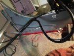
Since you have the same motor as me, i'm hoping you can answer some fuel line questions. Do you need a primer bulb? What size hose is needed for the fuel line? i'm thinking 3/8". Hose clamp on the motor end? Moeller offers a kit that i have heard mixed reviews on. What did you do for yours? Any info to help would be greatly appreciated! I'm new to the newer larger 4 strokes and have heard conflicting arguments to all these questions.
 

oldhaven

Chief Petty Officer
Joined
Aug 30, 2015
Messages
568
No primer bulb required. I have a fuel filter and water separator in the line and I filled that up before first start after installing the lines, so you have about a pint of fuel right near the motor. The line I am using right now comes from up in front of the boat and no problems, even with a couple of dips that could mean air lock. You do have a purge tap in the injectors line that you can use to fill the lines, just open it with a drain hose and turn on the key a couple of times without starting and the motor's fuel pump should prime the system. You should be able to buy a schroeder valve equipped hose to fit the tap. Mine ran a bit rough for a few seconds, but is good until the line is broken again. This should be outlined in the users manual. (one advantage of a new motor is that it comes with one.) The motor should have come wth two motor fuel hose barbs, a 1/4 and 3/8. I used the 3/8 and an unbroken length of approved for ethanol 3/8 fuel hose. I used a regular but good quality hose clamp at the motor. I got the Moeller kit but since it is universal basically it did not work so well, so I used parts of it and got new parts where required.

Ron
 

BMerr509

Petty Officer 2nd Class
Joined
Jun 28, 2016
Messages
167
I should preface this with a thanks to OH- this is exactly what i'm looking for.

The line I am using right now comes from up in front of the boat and no problems, even with a couple of dips that could mean air lock. You do have a purge tap in the injectors line that you can use to fill the lines, just open it with a drain hose and turn on the key a couple of times without starting and the motor's fuel pump should prime the system. You should be able to buy a schroeder valve equipped hose to fit the tap. Mine ran a bit rough for a few seconds, but is good until the line is broken again. This should be outlined in the users manual. (one advantage of a new motor is that it comes with one.) The motor should have come wth two motor fuel hose barbs, a 1/4 and 3/8. I used the 3/8 and an unbroken length of approved for ethanol 3/8 fuel hose.

Ron

When you say "a couple of dips", do you mean in the line? i would like to eliminate my potential for air lock if possible. I'll have to check the owners manual and see what it says. I'm guessing the purge tap is outlined in the manual as well. I'm really confused when you start talking about the tap. I get what you're saying to turn the key to get the pump to prime the line though.

Here is the one i'm thinking: http://www.iboats.com/MarPlate-Fuel-...view_id.980867

This seems simple to all you guys i'm sure but i'm very foreign to this. Watch me closely! I'll try to get good pictures when i run these lines. Seems simple- run line from tank to motor, with a fuel/water separator filter, clamp at every barb.

I'd like to put a shutoff valve in the line near the tank to be able to run the motor out of gas when i'm done for the day- should be simple right? How do you guys run your motors out of gas?

Unfortunately this is a part of the restoration it seems most of the guy skim over- i'm guessing its because it's straightforward.
 

oldhaven

Chief Petty Officer
Joined
Aug 30, 2015
Messages
568
The dips I refer to are places where the line runs over things then goes below that level. Just a few inches This has not been a problem. The tap I mentioned is what looks like a tire inflation valve in the injector feed line between the top two cylinders. It is really a bleed valve or purge valve for air. they weren't as smart as they could have been since it is below the tops cylinder and that is why it ran a bit rough at first start. Don't run the motor out of gas after use. It is injected so it has no float bowls and is a sealed system. It is just like a fuel injected car and you would not want to run your injector lines dry in your nice new car. these new motors are something different than the old leaky two strokes. I have two fuel tanks so I have a selector valve with a shutoff right after the filter so I can switch tanks, but I don't use it to stop fuel flow except for breaking the lines for maintenance, and i haven't done much of that. You won't have to do much all season except fill the tank and turn the key.

Ron
 

BMerr509

Petty Officer 2nd Class
Joined
Jun 28, 2016
Messages
167
Thanks for the explanation Ron, I think i got it now. I see they did include the 1/4" barb now. I'll read through the owners manual too.

Got some good progress this morning but ran out of aluminum, i'm about 6 ft short. oh well. it's complete enough to cut out the flooring/vinly, by the time im done with that the new aluminum will be here and i can finish it off proper. Take a look. i used the original splashwell but cut it on the sides. In order to know how far to place the aluminum splashwell on my boat, i put the motor fully trimmed and gave myself about 3" to spare. It came out alright, i have to bend the aluminum a bit more but once the floor is on that will all be a moot point. I need some more of the larger rivets too. some pics of the underside of the splashwell. One pic of the bilge install, which i bought a new hose for. its very rigid and kinked a touch but it will work and allows air to pass. I tested it out before i installed it too. The rest of the pics should be self explanatory. I doubled up the angle on the sides and in the middle.

Let me know what you think the strength will be. I know Rob said it was overkill. The marina was concerned the motor would pull the transom right off before i put all this framing on. I hope that can be alleviated now.

Have a great saturday. Was 60 here this morning now we are down to high 30s.
 

Attachments

  • IMG_0049.JPG
    IMG_0049.JPG
    98.4 KB · Views: 2
  • IMG_0050.JPG
    IMG_0050.JPG
    100.1 KB · Views: 2
  • IMG_0051.JPG
    IMG_0051.JPG
    89 KB · Views: 2
  • IMG_0052.JPG
    IMG_0052.JPG
    115.2 KB · Views: 2
  • IMG_0053.JPG
    IMG_0053.JPG
    81.4 KB · Views: 2
  • IMG_0054.JPG
    IMG_0054.JPG
    75.6 KB · Views: 2
  • IMG_0055.JPG
    IMG_0055.JPG
    95.3 KB · Views: 2
  • IMG_0056.JPG
    IMG_0056.JPG
    88.1 KB · Views: 3
  • IMG_0057.JPG
    IMG_0057.JPG
    88.4 KB · Views: 7

Watermann

Starmada Splash of the Year 2014
Joined
Jan 12, 2013
Messages
13,753
Hey you're moving right along with the back deck framing. :thumb:

Question, so where are the splashwell drain tubes?

fetch
 

BMerr509

Petty Officer 2nd Class
Joined
Jun 28, 2016
Messages
167
Thanks Rob. Great question- I planned on drilling a new one. Because the original is too low.
 

MD28

Petty Officer 1st Class
Joined
Sep 1, 2016
Messages
222
Looks great BMerr! Ill be watching if you don't mind. I like the casting deck idea from Candutch. Hopefully ill be doing the same with mine. What size rivets are you using to attach the angle?
 

BMerr509

Petty Officer 2nd Class
Joined
Jun 28, 2016
Messages
167
Hey MD- sure thing, take as much info from my thread as possible!! The rivet size is a loaded question- to connect 1/8" angle to 1/8" angle I'm using 1/8" diameter rivets with a grip length of 1/4", but the angle has to be perfectly flush in order for them to work. Which is why I also have 3/16" rivets that have a 1/2" grip length. For the angle that ties into my deck, I use 3/16" rivets with a grip length of 1-1/4". When I put the rivets into the floor, they are remarkably strong! All done with a hand rivet gun. The hardest part about this is making sure everything is square and symmetrical. It's difficult because there's no reference point. Fortunately the floor covers almost all of it up. I just make sure everything is square to the floor. Any other questions let me know.
 

BMerr509

Petty Officer 2nd Class
Joined
Jun 28, 2016
Messages
167
Got some more done. Not pictured, i got my transom eyebolts installed. Ordered all my wiring and accessories, as well as the rest of my aluminum angle. Installed my fuse block and switch panel. Question on the switch panel. My intention was to go from the accessory--->Fuse block----->switch panel. or from the switch panel to the fuse block. The problem is the switch panel only allows one input wire (+) for each switch. I guess the switch panel hooks into the fuse block and is fused by one terminal. I'm a mechanical guy, not an electrical guy haha i was baffled though. Anyways, here are the pics. Do not ask how i cut out the dash for the switch panel. I would lose the respect of some members here lol i put the fuse block on the inside portion of the console and secured via rivets.

IMG_0058.JPG
IMG_0059.JPG
IMG_0060.JPG
IMG_0061.JPG
IMG_0062.JPG
 

Watermann

Starmada Splash of the Year 2014
Joined
Jan 12, 2013
Messages
13,753
Got some more done. Not pictured, i got my transom eyebolts installed. Ordered all my wiring and accessories, as well as the rest of my aluminum angle. Installed my fuse block and switch panel. Question on the switch panel. My intention was to go from the accessory--->Fuse block----->switch panel. or from the switch panel to the fuse block. The problem is the switch panel only allows one input wire (+) for each switch. I guess the switch panel hooks into the fuse block and is fused by one terminal. I'm a mechanical guy, not an electrical guy haha i was baffled though. Anyways, here are the pics. Do not ask how i cut out the dash for the switch panel. I would lose the respect of some members here lol i put the fuse block on the inside portion of the console and secured via rivets.

Switch panels are simple, each switch has 2 terminals. 1 terminal is fused power from the block and the other terminal is for where the power is sent when switched on and is connected to the device needing power.

I used 12 ga wire (20 amp) to supply the power and ground to my block and 16 ga for the devices to be powered and grounded. Gauges are daisy chained power (lights) and ground. My pumps, lights, horn and such are fused at their rating. I did use 12 ga with 20 amp fuse to my power point receptacle in the switch panel just in case I use a spotlight or something else that takes max power.
 

BMerr509

Petty Officer 2nd Class
Joined
Jun 28, 2016
Messages
167
Thanks Rob. Found the issue. The switch panel manufacturer daisy chained one of the two terminals, which is supposed to go directly to the battery (+). I'll need to remove that daisy chain to free up the second terminal on each switch and run that to my fuse block to ensure i'm fused properly per accessory. I hope you follow that.
 

Watermann

Starmada Splash of the Year 2014
Joined
Jan 12, 2013
Messages
13,753
Yeap I do understand, mine was the same way and I tossed their chain in the spare wiring box.
 

BMerr509

Petty Officer 2nd Class
Joined
Jun 28, 2016
Messages
167
Yeap I do understand, mine was the same way and I tossed their chain in the spare wiring box.


HAHA that makes sense to me! Thanks for the assist on this one.

I'm hoping to actually make a splash mid march, just with the tech to ensure the motor runs. Key areas for me now are completing the rear casting deck for the additional strength, fuel tank installation and getting my new trailer, as well as ensuring i have all the right safety equipment needed per NYS law. The electrical will take me a full day. With this weather, one could fish for browns in the first week of april!
 

Tnstratofam

Commander
Joined
Aug 18, 2013
Messages
2,679
Do not ask how i cut out the dash for the switch panel. I would lose the respect of some members here lol i put the fuse block on the inside portion of the console and secured via rivets.

I see a hammer and wide chisel laying on deck, but I'm sure these weren't the tools used.:rolleyes:


Just messin with ya.:D The switches look good by the way!:thumb:
 

BMerr509

Petty Officer 2nd Class
Joined
Jun 28, 2016
Messages
167
Thanks Tn, i guess since this is a forum for knowledge i should let people who don't have all the tools in the world (like me) know how i cut out the slot for the panel.

I do have a jigsaw, but as you can see, there is not much clearance from the cutting area to the gunwhale, not to mention the steering wheel is also in the way. So what i ended up doing was drilling out the cutout- literally drilled 50 holes in the form of a rectangle and in comes hammer/chisel to pop it out. Then i took my dremmel tool and sanded the edges. I put a layer of epoxy on it before mounting the panel, and around the panel i put a good bead of 5200. I'm less concerned about water intrusion on anything that is not the floor. You cannot cut it from the backside due to cables/wiring.

Moral of the story- get your dang switch panel mounted before you put your steering cables/wheel on!!!! :facepalm: :star:
 

Pusher

Lieutenant
Joined
Sep 2, 2014
Messages
1,273
Looks good from where I'm at! You've got to get it done one way or another right?
 

Watermann

Starmada Splash of the Year 2014
Joined
Jan 12, 2013
Messages
13,753
Thanks Tn, i guess since this is a forum for knowledge i should let people who don't have all the tools in the world (like me) know how i cut out the slot for the panel.

I do have a jigsaw, but as you can see, there is not much clearance from the cutting area to the gunwhale, not to mention the steering wheel is also in the way. So what i ended up doing was drilling out the cutout- literally drilled 50 holes in the form of a rectangle and in comes hammer/chisel to pop it out. Then i took my dremmel tool and sanded the edges. I put a layer of epoxy on it before mounting the panel, and around the panel i put a good bead of 5200. I'm less concerned about water intrusion on anything that is not the floor. You cannot cut it from the backside due to cables/wiring.

Moral of the story- get your dang switch panel mounted before you put your steering cables/wheel on!!!! :facepalm: :star:


Yeah I had the method figured out when I saw this pic below... :lol:

Good moral to the story, I set up my dash panel with gauges and switches in the house at the dinner table. :heh:

fetch
 

Tnstratofam

Commander
Joined
Aug 18, 2013
Messages
2,679
I am guilty of using whatever I have on hand to get the job done. Usually I find out the correct tool for the job long after I've beat myself and whatever I'm working on to death.:facepalm: I think most of my tool box ended up in the boat with me at some point all at the same time while I was replacing the transom in our SS.

The dash still looks great no matter how you installed the switches.:encouragement:
 

BMerr509

Petty Officer 2nd Class
Joined
Jun 28, 2016
Messages
167
Thanks!!! It's pretty much the same from me. My garage basically is a mess and has been since July haha
 
Top