1976 Chrysler 105 - winter project

Frank Acampora

Supreme Mariner
Joined
Jan 19, 2007
Messages
12,004
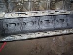
Unless they are visibly worn, rings need not be replaced. Remember: They get a fresh shot of oil each revolution and outboards generally get little use compared to an automobile. Rings very rarely wear to the point of needing replacement. Measure the bores before you do anything. Chrysler tolerance for wear, barrel shape and taper was only .002. If out of tolerance, a bore job and oversized pistons are required. Note that during the same period OMC set tolerance at .005 so if you want to gamble---- Stock bore was 3.3125 inches. Stroke was 2.80 inches for a total displacement of right around 99 cubic inches.

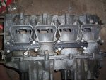
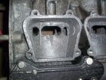
The 105 came equipped with smaller 1 5/16 diameter venturi WB carbs. You can remove the manifolds and replace with manifolds,reeds, and TC carbs.(1 3/8 diameter venturi). These can be found on any Force 120 or 125. They also came on SOME Chrysler 120 and all 125 and 140. You won't get 120 horsepower but you will get an honest 90 at the prop.

The 105 was made for many years and was rated at the powerhead, Back in , I think, 1982 NMMA mandated that ALL outboards were to be rated at the prop. Chrysler took the 105 and with no changes other than decals called it a 90. Thus the reasoning for the honest 90 HP statement.

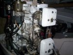
I don't see your distributor but in 1976 it should have had an electronic one. If it does not you can get a slight performance gain by swapping in an electric eye dist. They are more precise and you don't need to worry about setting points or point bounce.

If you keep the distributor do not set the belt tension too tight. If you do, believe it or not, you will have shifting problems. To set belt tension an .010 feeler gauge when pressed to the center of the belt should deflect the belt about 3/16 inch before bending. You can set the timing to 30 Degrees BTDC and be safe but the engine really likes to run at 32 BTDC. If you do that be certain to use only street auto pump gas so you are sure of the octane.

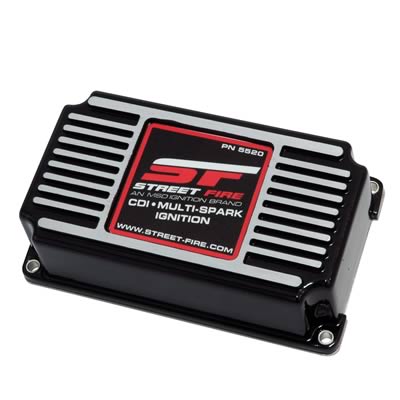
You also have the option of converting to Prestolite non-distributor ignition. It requires all ignition components, flywheel and stator mount. You will need to drill and tap 5 holes to install the stator mount and you will need a special thick washer under the mount to keep the top bearing from riding up. I don't know if this washer is still available but I do know that some Force 40 engines did have it. At any rate, a good machine shop should be able to make one relatively cheaply.
 
Last edited:

Frank Acampora

Supreme Mariner
Joined
Jan 19, 2007
Messages
12,004
No Title

Here are a couple of photos of a 105 block that I am currently working. I have tried to replicate the porting of the Force 150. Since the #3 and #2 cylinders fire right next to each other into a common exhaust cavity extra port area may be counter-productive. (Firing order 1, 3,2,4) Since I have obviously not yet tried this engine I can not recommend this type exhaust porting. However, I have so many of these blocks that if one experiment does not work, I simply do not use it.

I can say that the stock 105 with large TC carbs did drive my 15 foot Glastron V153 at about 45 MPH at someplace between 5000 and 5500 with a 19 pitch prop. Now, that is no guarantee and it was also with the one piece 2 to 1 lower unit and power TnT. You would expect 3-5 MPH slower (maybe more) top speed with your 2 piece lower unit.

Oh, yeah-- That's it at speed in my avatar
 

Attachments

  • photo234783.jpg
    photo234783.jpg
    212 KB · Views: 1
  • photo234785.jpg
    photo234785.jpg
    181.6 KB · Views: 1
  • photo234786.jpg
    photo234786.jpg
    204.2 KB · Views: 1
  • photo234787.jpg
    photo234787.jpg
    180.2 KB · Views: 1
Last edited:

Arawak

Chief Petty Officer
Joined
Aug 27, 2010
Messages
486
Well, I was able to borrow a cheap Harbour Freight dial caliper and determine that it has never been bored. In fact, it's pretty obvious the motor has never been opened up, the factory paint is all over the gaskets and the exposed thread, etc. The caliper was not accurate enough for me to determine whether it's 0.002 out, but the cylinders do not look that worn (in my limited experience) so I don't think this is a high hours motor. Christmas brings a better caliper :)

I don't know how to identify the distributor, but will post a photo later tonight.

But, my plan for the ignition is to try an MSD Street Fire. Should work with either style of distributor. Again, all in the interest of a learning exercise, and if it's successful it will be useful community knowledge. Kids can get me one for Christmas :)

Definitely want to port the intake side.

The TC carbs are worth a look for too.

So today I had no luck getting the flywheel off. Going to have to find a puller. But I did manage to get a fair bit of the rest of the motor apart. Looking through the intake side with a flashlight I can see that the piston skirts all appear to be fine:
image_234836.jpg
 

Attachments

  • IMG_20151129_182224.jpg
    IMG_20151129_182224.jpg
    128.4 KB · Views: 1
Last edited:

Arawak

Chief Petty Officer
Joined
Aug 27, 2010
Messages
486
I had my first casualty... one of the small screws on this port snapped:
image_234837.jpg


Maybe I can drill it out and tap when I get to putting it back.
 

Attachments

  • IMG_20151129_182224.jpg
    IMG_20151129_182224.jpg
    128.4 KB · Views: 1
Last edited:

Arawak

Chief Petty Officer
Joined
Aug 27, 2010
Messages
486
Frank, would a 125 Force like this provide the LU and carbs/manifold as suggested above:

force.JPG

It's a couple hours down the road from me
 

Frank Acampora

Supreme Mariner
Joined
Jan 19, 2007
Messages
12,004
Yes, it will work BUT---- You will need to use the midleg too Bolt pattern is way different than your 2 piece lower unit. Since you already have the engine block dismounted it is no sweat to swap.

Carbs and manifolds will also fit but again, if you use the reed Vee blocks, you will ned to grind down the bolt bosses on either side so they will seat properly. IF the reeds have four petals you will need to change the mounting screws to flat head so they will fit. Search my past posts to see how I had done this in the past.

For a puller, try a harmonic balancer puller or a steering wheel puller and while the center bolt is tight, heat the center of the flywheel with a propane torch.

Dang! I should have warned you about the water bypass cover screws. One will almost always break. In fact, On Force engines they got rid of this bypass and spring loaded valve.

Do be very careful with the exhaust cover bolts. Chances are very good that you will snap at least a couple.
 

Arawak

Chief Petty Officer
Joined
Aug 27, 2010
Messages
486
Thanks Frank. Should I apply a bit of gentle heat to the exhaust cover bolts before I try them?
 

Frank Acampora

Supreme Mariner
Joined
Jan 19, 2007
Messages
12,004
Our friend heat can sometimes help. Sometimes these bolts will back out about 1 turn then gall. Rocking them back and forth may sometimes break the corrosion grip. Sometimes the vibration of an impact gun will work them out without harm.

Once loose, soaking with penetrant may also help. However, sometimes you are just going to snap one. Expect it and consider yourself lucky if you don't.

There is so much depth to these castings that you need not worry about drilling slightly off center. Drill out the remainder of the bolt and drill deeper. Just be careful: A deep drill into aluminum may gall and snap the drill bit. Then you are skunked. Drill in steps, withdrawing the drill and clearing chips, drill slowly and use plenty of lubricant. Same goes for tapping 1/4-20. Then use a longer bolt

BTW: If you like the cover and other tins better than the Force, all your white stuff will swap. And you can fill in the hole in the side of the block where the relief valve is. Just be certain that the water feed hole is clear. Remember I said that Force engines did not have this bypass?

I can't quite tell from the photo but that Force looks like a 25 inch leg--be aware if you intend to put on a hull with a 20 inch transom.

Oh, yeah---Electric eye distributor has two wires on posts at the front of it. It may have a decal saying "ELECTRONIC" Points distributor only has one wire. When you install the distributor be certain that there is a ground wire from the distributor body to the mount on the block. A ground wire from the coil also attaches there.
 
Last edited:

Arawak

Chief Petty Officer
Joined
Aug 27, 2010
Messages
486
My dad left his puller at my house during the day. Just got home, hooked it up, but before I start tightening, is this (below) a bad idea? I can make a plate to screw into the three holes if needed.

IMG_20151130_165448.jpg
 

Attachments

  • IMG_20151130_165448.jpg
    IMG_20151130_165448.jpg
    110.1 KB · Views: 1

fisheymikey

Chief Petty Officer
Joined
Jul 30, 2012
Messages
450
hi Arawak... glad to see maybe i could help.
some ppl have done it that way but the also have sometimes broke the magnets due to pressure increasing on the extremities.
i used a steering wheel puller with great success.. the trick is appy a good amout of pressure on the puller and give a sharp wak! with a small mass. the vibration will separate the suborn flywheel. i have the screws and bolts that go into the flywheel, mine is a force 12 but i think they are both the same.

if you dont have one i send you mine will only cost you shipping it back to me.

let me know

mike
 

Arawak

Chief Petty Officer
Joined
Aug 27, 2010
Messages
486
Ah, glad I asked :)

I'll hunt around... surely one of my friends will have a steering wheel puller. But if not, I might take you up on your kind offer.

Thanks!
 

Frank Acampora

Supreme Mariner
Joined
Jan 19, 2007
Messages
12,004
Bad idea! Look at the angle of the arms-they are not putting upward pressure. As said, steering wheel puller or harmonic balancer puller. You can make a plate of about 3/8 steel and use the three bolt holes. Apply a bit of heat with the pressure on and then whack it with a heavy hammer. If the three holes strip, simply re-tap to 5/16.
 

Frank Acampora

Supreme Mariner
Joined
Jan 19, 2007
Messages
12,004
No Title

Plate is 3/8 thick and center screw is fine thread 1/2 inch grade 8 bolt. If you look closely you will see that there is a 1/2 inch flange nut in the center. The hole was already there and too large so I pressed in the nut. The flange is underneath so the nut will not pull through. Make do with what I have!
 

Attachments

  • photo234993.jpg
    photo234993.jpg
    192.8 KB · Views: 1
Last edited:

Arawak

Chief Petty Officer
Joined
Aug 27, 2010
Messages
486
Oooooh... I love me a homemade tool! Another excuse to break out the welder too :)
 

oldboat1

Fleet Admiral
Joined
Apr 3, 2002
Messages
9,598
will secure that powerhead? going to rap the puller bolt pretty good.
 

Arawak

Chief Petty Officer
Joined
Aug 27, 2010
Messages
486
Well, harmonic balancer puller has been located and I'll have it tomorrow. Not much else I can do until I get the flywheel off, so tonight I *carefully* removed the exhaust cover. Luck was on my side, no bolts snapped! :happy:

So there are two gaskets and a steel sheet between the cover and the exhaust chamber. Is the steel sheet a consumable or do I re-use it? Can't find a mention of it in my service manual, so maybe it's just a gasket?

IMG_20151201_185923.jpg

Still no sign of my loose screw. Nor is there any really obvious damage on either the intake or exhaust side. :noidea:
 

Arawak

Chief Petty Officer
Joined
Aug 27, 2010
Messages
486
In other news my ignition turned up today. I held it in my hands before giving it over to the wife to wrap up for christmas :)

msd-5520_w.jpg

If I actually get it working it will move over to the working 105 on my Bayliner.

Or I'll buy another :)
 
Last edited:

Frank Acampora

Supreme Mariner
Joined
Jan 19, 2007
Messages
12,004
Even though the stainless sheet is warped and has lots of crud on it, it can be reused. It is stainless because one side of it is directly impinged by hot exhaust gases. The other side is cooled by water. However, because exhaust gases are corrosive (and that's why it is stainless) check the plate for perforations before you use it again. Water flow is from the bottom of the chamber above the pressure relief valve, then through the exhaust chest walls. Then it passes through the triangular shaped hole and the upper holes in the aluminum cover into the block surrounding the cylinders. Lastly it passes through the thermostat and down the head. Finally it passes out the rectangular hole in the bottom of the head and down the midleg to be partly exhausted and partly out the rear idle relief holes.

Very often the gaskets break when you remove the cover. When replacing it be very careful at the "dogleg" at the bypass. This is thin and can easily kink or break leaving you with a water leak. This goes for new and used gaskets. At this point I do not know if new gaskets are available for that cover--note that it has many more bolts than a Force exhaust cover.

Run a 1/4 X 20 tap down each mounting bolt hole. The original bolts are relatively short so it is preferable to find slightly longer ones. Use anti-seize and torque only to 70 inch pounds.Remember you are tightening into aluminum and a stripped bolt hole is a PITA.

If you use the Motorola ignition, run a thin aluminum plate over the wires and under the flywheel. These wires tend to bounce up into the flywheel, rubbing and shorting. The engine dies for apparently no reason and you are left scratching your head because it will start and run for a period of time before it happens again.
 
Last edited:
Top