Wiring help

DefiantDad

Cadet
Joined
Sep 14, 2024
Messages
13
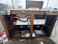
Curious before I clean everything up and finish routing wires if I am doing something wrong and looking for input.

30' pontoon with 3.0 Mercruiser 3 batteries 1 starting, 2

House Mini add a battery

I have two house batteries tied together running to my switch then to a buss bar and the start battery going to other side of switch then to starter. All three batteries ground to a common ground bar. The M-ACR Is wired one side to each battery. And the ground is to the ground bar, start isolation to the keyed start switch on the dash.

House has a main fuse, buss bar runs to a fuse panel under console for individual items, amp & inverter have inline fuses.

The alternator wire is going to one of the house batteries.

Forget where I read to do it on house side but didn't think it would hurt.

All house items ran to buss bars.

Am I doing this right? Thanks for any insightIMG_8152.jpeg
 

ESGWheel

Chief Petty Officer
Joined
Aug 29, 2015
Messages
479
I am going to take a stab here as I am currently developing my plan to add a house battery with an ‘Add A Battery’ ACR. While your description sounds ok it’s hard to tell without a wiring diagram. Can you generate one? Even if it’s a hand drawn and a clear picture taken and posted that will help. BTW, I think you got the ‘connect to the house side’ fm the 7650 Instructions vs. the 7649 which is the Mini Add a Battery which shows it to the start battery, see pic. But I am not sure I fully understand your set up. Is the 3.0 an inboard in a pontoon?
 

Attachments

  • Mini Add A Battery.png
    Mini Add A Battery.png
    75.9 KB · Views: 6

DefiantDad

Cadet
Joined
Sep 14, 2024
Messages
13
I am going to take a stab here as I am currently developing my plan to add a house battery with an ‘Add A Battery’ ACR. While your description sounds ok it’s hard to tell without a wiring diagram. Can you generate one? Even if it’s a hand drawn and a clear picture taken and posted that will help. BTW, I think you got the ‘connect to the house side’ fm the 7650 Instructions vs. the 7649 which is the Mini Add a Battery which shows it to the start battery, see pic. But I am not sure I fully understand your set up. Is the 3.0 an inboard in a pontoon?
Heres my schematic 😂 dont judge my artistic skills.

The 3.0 is a inboard/sterndrive motor. 4cyl.
 

Attachments

  • IMG_8190.jpeg
    IMG_8190.jpeg
    1.2 MB · Views: 10

ESGWheel

Chief Petty Officer
Joined
Aug 29, 2015
Messages
479
The 3.0 is a inboard/sterndrive motor. 4cyl.
Makes sense, was wondering how you connected Alt. output to House side :)
Heres my schematic 😂 dont judge my artistic skills.
I'll print it out and take a look and get back to you. I am going to assume wire sizing is correct but if you are concerned about that mark it up with the wire gauge sizes...
 

DefiantDad

Cadet
Joined
Sep 14, 2024
Messages
13
Makes sense, was wondering how you connected Alt. output to House side :)

I'll print it out and take a look and get back to you. I am going to assume wire sizing is correct but if you are concerned about that mark it up with the wire gauge sizes...
Thank you wire should be fine its probably a size larger than needed across the board
 

DefiantDad

Cadet
Joined
Sep 14, 2024
Messages
13
Makes sense, was wondering how you connected Alt. output to House side :)

I'll print it out and take a look and get back to you. I am going to assume wire sizing is correct but if you are concerned about that mark it up with the wire gauge sizes...
I forgot to add the 100amp inline breaker between switch and battery buss bar on the house side
 

ESGWheel

Chief Petty Officer
Joined
Aug 29, 2015
Messages
479
First off, looks ok and I see you elected to have the “ACR” Off switch installed on the ACR Gnd. Some follow up questions:
  • Do you have appropriately sized ckt breakers and fuses where needed? I do not see any in your picture in post 1.
There is a 1000W inverter.
  • Is it an Inverter / Charger?
  • What is the Inverter for?
  • Do you have Shore Power as well?
It looks like the batteries are all the same lead acid chemistry and same size, please confirm.

PS: jsut saw your post 6, can you mark with an x on your drawing where you have fuses / breakers and indicate size please and repost. thx.
 

DefiantDad

Cadet
Joined
Sep 14, 2024
Messages
13
First off, looks ok and I see you elected to have the “ACR” Off switch installed on the ACR Gnd. Some follow up questions:
  • Do you have appropriately sized ckt breakers and fuses where needed? I do not see any in your picture in post 1.
There is a 1000W inverter.
  • Is it an Inverter / Charger?
  • What is the Inverter for?
  • Do you have Shore Power as well?
It looks like the batteries are all the same lead acid chemistry and same size, please confirm.

PS: jsut saw your post 6, can you mark with an x on your drawing where you have fuses / breakers and indicate size please and repost. thx.
All the house items except the inverter and amp are ran to the console where theres a fuse block that has everything routed off of. The amp has an inline fuse as does the inverter and there is a 100amp breaker between the switch and the house buss bar. I can annotate when i get home on the drawing.

The inverter is only to power my Trager Roadie grill and a inflatable pump for the tube and such.

All batteries are the same, no shore power
 

ESGWheel

Chief Petty Officer
Joined
Aug 29, 2015
Messages
479
Cool, so far looking good IMO. 2 things in my mind still to tease out (1) the marked up dwg with fuses and (2) should the AC Ground also be bonded to the DC Neg side? If there was shore power the answer is yes, but I cannot (yet) find if should be if inverter only. However, I think yes, as in the DC neg needs to attach to the chassis of the inverter in case there is fault in the inverter. Did your inverter instructions provide any guidance in that area? Do you have DC Neg attached to the inverter case?
 

DefiantDad

Cadet
Joined
Sep 14, 2024
Messages
13
Cool, so far looking good IMO. 2 things in my mind still to tease out (1) the marked up dwg with fuses and (2) should the AC Ground also be bonded to the DC Neg side? If there was shore power the answer is yes, but I cannot (yet) find if should be if inverter only. However, I think yes, as in the DC neg needs to attach to the chassis of the inverter in case there is fault in the inverter. Did your inverter instructions provide any guidance in that area? Do you have DC Neg attached to the inverter case?
Yes it is a small jumper basically from the inverter chassis to the ground its how the manual instructed.
 

DefiantDad

Cadet
Joined
Sep 14, 2024
Messages
13
Cool, so far looking good IMO. 2 things in my mind still to tease out (1) the marked up dwg with fuses and (2) should the AC Ground also be bonded to the DC Neg side? If there was shore power the answer is yes, but I cannot (yet) find if should be if inverter only. However, I think yes, as in the DC neg needs to attach to the chassis of the inverter in case there is fault in the inverter. Did your inverter instructions provide any guidance in that area? Do you have DC Neg attached to the inverter case?
Heres the main fuses/breaker. I will draw up the console fuse panel if needed also
 

Attachments

  • IMG_8198.jpeg
    IMG_8198.jpeg
    1.7 MB · Views: 5

ESGWheel

Chief Petty Officer
Joined
Aug 29, 2015
Messages
479
Here are my thoughts:
It seems your fuse and bkr sizes may be too small. Example your 1000W Inverter could draw 1000W/12V = 83 Amps and for a short burst a lot more. But that is only one factor. The Wire Size is also a determining factor. Here is a link to the Blue Sea website that walks thru that process (link). Scroll down to “Choosing the Fuse Amperage” that walks thru the max (based on wire size) and min (based on the product i.e., inverter or the amp) and splitting the difference.

The m-ACR instructions include a recommendation for fusing between the ACR and the Batteries, which you have left off. Recall that fuses are also meant to protect the wiring. They are also left off of the Gnd wire and the Start Isolation.

Is the console fuse panel a factory installed or did you do it? Either way ensure that the Neutral and Gnd are NOT bonded at the panel. This bonding needs to occur at the source of the AC, in this case the inverter (which is does for you). And if the panel itself is metal, it needs to be grounded. Additionally, the breakers on the panel are more than likely single pole (interrupt the hot and not the hot + neutral). No issue with that but need to ensure downstream outlets are polarized and if you hardwired a device into the panel the black was to black and white to white (which you know already but well to double check). Also ensure any connected AC device does not have its ground and neutral bonded internally. They should not be and its best (and easy) to check.

I looked at the picture again and there is an extension cord plugged into the inverter. Is this your power to the AC panel? That does not seem good.

And while I have learned to not post past my bedtime, let me conclude tonight’s session with this disclaimer. I am not an ABYC certified electrician. I am simply passing along knowledge of what I have gained and want seems reasonable based on my experience. And I am willing to share. One of those experiences is knowing how much potential energy 3 x Lead Acid Batteries contain. It’s a surprising amount especially when expelled in a very short time. So, prior to starting up this system, recommend having a qualified ABYC electrician look it over.
 

ESGWheel

Chief Petty Officer
Joined
Aug 29, 2015
Messages
479
After a night’s sleep I realize that you must have been talking about your OEM installed DC dist. panel, not an AC one. No, do not need to see that. And for the extension cord I also think that you are directly using that for our pellet BBQ, which only has a small wattage fan on it and the toy inflator, ie, there is no AC panel. Correct?
 

DefiantDad

Cadet
Joined
Sep 14, 2024
Messages
13
After a night’s sleep I realize that you must have been talking about your OEM installed DC dist. panel, not an AC one. No, do not need to see that. And for the extension cord I also think that you are directly using that for our pellet BBQ, which only has a small wattage fan on it and the toy inflator, ie, there is no AC panel. Correct?
Correct there is no AC panel and the “extension cord” is a flush mount waterproof housing 110v type outlet so i can plug in on the outside of the compartment vs directly into the inverter.

Yes the factory dc fuse panel in the console.

I completely overlooked the fuses for the M-ACR and will get those installed.

The AMP and the Inverter both are ran with 4 gauge, the batteries, starter and feeder to buss bar are ran with 00 and the alternator and m-acr is 8 gauge
 

ESGWheel

Chief Petty Officer
Joined
Aug 29, 2015
Messages
479
Thanks for posting the wire sizes and I was finally able run the calculation of needed wire size using this link. Here is what I found:
  • Amp and inverter at 4 seems fine. Based on 85A, 15 feet of run, 12VDC and 3% drop yields 4G. Is 15 feet, correct? From the picture it seems less than that but I used it as a conservative value.
  • Starter and Bus Bar Feeder at 00 also seems fine. Based on 225A, 15 feet of run, 12VDC and 3% drop yields 00. Is 15 feet, correct? Unsure but it seems reasonable.
  • Alt and m-ACR at 8 seems a little small. Based on 55A, 15 feet of run, 12VDC and 3% drop yields 6. While the 15 feet is probably about right, I am usure of your alternator output. One website I looked at said its was a 55A alt, another said higher, like 85. If the 8 was based on the existing alt wire, you are probably ok unless you had to extend the length significantly.
Recommend you run the numbers yourself with the actual lengths and for the Alt the max output if not already done.

Also recommend post commissioning the system crank that stereo and fire up that grill and after an hour or so, go back and feel the inverter and amp wires. Are they hot? That is an issue. And keep that stereo cranked, have fun and run down those house batteries so they need a good charge. Then after you return to port, same thing: feel the Alt and ACR wires…

Please post how it goes.
 

DefiantDad

Cadet
Joined
Sep 14, 2024
Messages
13
Thanks for posting the wire sizes and I was finally able run the calculation of needed wire size using this link. Here is what I found:
  • Amp and inverter at 4 seems fine. Based on 85A, 15 feet of run, 12VDC and 3% drop yields 4G. Is 15 feet, correct? From the picture it seems less than that but I used it as a conservative value.
  • Starter and Bus Bar Feeder at 00 also seems fine. Based on 225A, 15 feet of run, 12VDC and 3% drop yields 00. Is 15 feet, correct? Unsure but it seems reasonable.
  • Alt and m-ACR at 8 seems a little small. Based on 55A, 15 feet of run, 12VDC and 3% drop yields 6. While the 15 feet is probably about right, I am usure of your alternator output. One website I looked at said its was a 55A alt, another said higher, like 85. If the 8 was based on the existing alt wire, you are probably ok unless you had to extend the length significantly.
Recommend you run the numbers yourself with the actual lengths and for the Alt the max output if not already done.

Also recommend post commissioning the system crank that stereo and fire up that grill and after an hour or so, go back and feel the inverter and amp wires. Are they hot? That is an issue. And keep that stereo cranked, have fun and run down those house batteries so they need a good charge. Then after you return to port, same thing: feel the Alt and ACR wires…

Please post how it goes.
Thank you sir! The amp/inverter are only about 2.5ft from the buss bar the starter is 12ft and the m-acr is 4ft i will run the numbers this weekend and make sure all jives and will also rest out the calibrated touch method! Thanks again!!
 
Top