PLEASE HELP ASAP charging question

dsweet2010

Cadet
Joined
Jul 30, 2017
Messages
16
I have done extensive research and bought multiple rectifiers, which still test good, multiple batteries, now today put on a different stator. I still am not appearing to charge the batteries. the stator that I ordered that was supposed to be for my motor did look slightly different though . All the wiring is correct everything ohms out perfectly, resistance and diodes tests are all correct, and still no charging. The voltage does increased very slightly with RPM now but still only up to 12. 1 volts. Please look at these pictures and see if these two Stators should be compatible. They did bolt up exactly the same and have identical wiring. Dark one is the replacement stator. I just don't understand because that is every component all all replaced in checking good
 

Attachments

  • photo295172.jpg
    photo295172.jpg
    1.1 MB · Views: 0

Faztbullet

Supreme Mariner
Joined
Mar 2, 2008
Messages
15,902
Wells that a 6 amp stator so what your seeing at idle is normal. It will put 6amps at WOT,3 amps at 2500rpm and about 1 amp at idle. Anything over a 600CCA battery will charge slow.
 

oldboat1

Fleet Admiral
Joined
Apr 3, 2002
Messages
9,612
divided by two, if both batteries charging at once (e.g., battery switch set to both). When testing, begin with fully charged batteries.
 

sam am I

Commander
Joined
Jun 26, 2013
Messages
2,169
So yes, consider the above BUT, if you KNOW the battery is fully charged ahead of time (charged over night say with external charger) and the thing is working right, even with only a 6 amp stator AND while you running at 4K say, you should see it climb to 14V within a few minutes. If it has been gone through as thoroughly as you say and still not working AND with known charged battery, Last thing I guess is....Magnets okay?
 

dsweet2010

Cadet
Joined
Jul 30, 2017
Messages
16
Yes, flywheel and magnets all APPEAR to be good anyways. It starts right up and runs perfect, so I am assuming flywheel and magnets are all good.I am only seeing about 12.1 VDC at idle and only gets up to about 12.4 VDC at higher RPM (on water hose at home.) Using multimeter set to AC volts, each yellow wire out of stator only reads about 3.5 V to ground, Between both yellow from stator with motor running I only get about 15VAC at any rpm. I am thinking my replacement stator I bought used is indeed faulty as well??
 

Faztbullet

Supreme Mariner
Joined
Mar 2, 2008
Messages
15,902
Are you running dual batterys????? If so that motor will never charge them both.
 

sam am I

Commander
Joined
Jun 26, 2013
Messages
2,169
Yes, flywheel and magnets all APPEAR to be good anyways. It starts right up and runs perfect, so I am assuming flywheel and magnets are all good.I am only seeing about 12.1 VDC at idle and only gets up to about 12.4 VDC at higher RPM (on water hose at home.) Using multimeter set to AC volts, each yellow wire out of stator only reads about 3.5 V to ground, Between both yellow from stator with motor running I only get about 15VAC at any rpm. I am thinking my replacement stator I bought used is indeed faulty as well??


Wait as tick!!..........15VAC across the yellows? That is a good thing. Don't replace anything yet. That is a RMS measurement, so 15Vrms * 1.414 = 21.21 Vp and after two Si diodes (bridge rectifier) 21.21 Vp - (2*0.6) = 20VDC.

You have an open/reg/rec issue somewhere after those yellow wires still sir!...........Give us a hint man, what cha workn on plz? Can't help much more unless we know this.....

It sure can charge them both, with neglectable other loading (1, 2 amps for engine etc) and given time, see below. HOWEVER, during testing and to expedite this, if they're both charged up in advance, 6 A still should rise them both back up to 14'ish volts after a bit of time, say within 5/10 minutes max (I say this because given enough time, few days, whatever, or starting with good known charged up batts, even my/a 1.5 A trickle chargers can have 3 flooded lead in parallel to 14.3 volts within the hour, do it all the time but, again they're topped off as i hook them up)

FYI and FWIW, Any AC voltage measurement referenced to ground (engine block etc) should be invalid on those yellow charge wires due to the stators charge windings are typically floating (I'm not a Jonnyrude guy but, most charge windings are not ground referenced, so the 3.5V isn't real per-se I'd guess) HOWEVER, the 15VAC across the two yellows is valid and is definitely in the ball park....Press on young soldier, you're getting close.
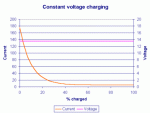
Click image for larger version  Name:	Image133.gif Views:	1 Size:	11.0 KB ID:	10609316


Alternators can be modeled as a constant voltage source, thus they charge with a constant voltage(but do have limited current---real world). OP's would only differ (if his were dis-charged'ish) here in that the voltage would sag at first due to current limiting (6 amps, real world) but, in time, the current draw would decrease to less then the limited 6 amps, the voltage then would have climbed to be around 14V at this point, the current draw then begins to tapper off slowly as time passes to nearly zero amps (see graph).......This is independent of battery capacities (paralleled etc)
 
Last edited:

dsweet2010

Cadet
Joined
Jul 30, 2017
Messages
16
I am so sorry that I have yet to mention my motor lol. It is a 1974 Johnson 70 Hp. Maybe perhaps I do not still have a charging issue and need to take it out and run it a while. I did have a dual battery setup on a selector switch, but through this process I have eliminated everything down to running on a single battery to find this issue. After multiple rectifier replacements and now a stator replacement, I am just basing my not charging assumption by the voltmeter on the dash only reading 12 volts after start up in the driveway . Also whenever I activate running lights or Electronics my Dash immediately reads 9-10V. Maybe it just needs to run a while to catch up from my understanding now??
 

F_R

Supreme Mariner
Joined
Jul 7, 2006
Messages
28,224
Running lights make it drop down to 9-10V??? That ain't right. First thing I'd suspect is a high resistance in the wiring between battery and supply to the lights. Don't have a wiring diagram for the boat, so only guessing.
 

sam am I

Commander
Joined
Jun 26, 2013
Messages
2,169
Hang on and ty for the info, it helps, also agree with F_R..........Go back to that AC measurement from "ground" to either of the yellow or yellow/gray stator wires.........I must make a retraction

You should in fact measure around 12VAC from ground (not "3.5 V to ground") on each yellow wire........Start the engine, let it idle'ish but, this time, and again, using your AC voltage meter, check your voltage from the metal body of the rectifier (ground) to each yellow wire plz.........You should see 12'ish VAC for both yellows. Next, take the one meter lead from the body of the rec and move it to the engine block, checking again both yellows, should be same...That is, if the rectifier is grounded properly.

12VAC across the two yellows from #8 is good and tells me the stator is ok and producing but, doesn't tell the whole story down stream quite yet, of which, I believe we are close to knowing.
 
Last edited:

dsweet2010

Cadet
Joined
Jul 30, 2017
Messages
16
Yes I am getting 15.5VAC between 2 terminal as shown in pic below, but each individual lead to ground is only 3.5vac . I'm going to play with it some more tonight after work . I'm going to remove all wiring associated to the boat and jump the starter to eliminate any cross issues going on from the boats wiring . at this point it would not make sense but I would not be surprised if it is something in the boat wiring as I just restored the pontoon and wired everything completely myself. I am very good with wiring, but there may be something funny along the line that I was not aware of in the outboard world?? Also keep in mind I do not have a DVA adapter so these readings are direct from a regular multimeter .
 

Attachments

  • photo295445.jpg
    photo295445.jpg
    1.2 MB · Views: 0

F_R

Supreme Mariner
Joined
Jul 7, 2006
Messages
28,224
If you are good with wiring, you know that a resistance in a circuit will cause a voltage drop as a current passes through it. That's what I was trying to say above. You have a charged (nominal) 12V battery and a puny current (running lights), and 2 or 3 volts drop because of it. That can only mean a couple of things.

There is a high resistance between the source and where you are reading the voltage.
There is much more than the running lights' current flowing--would probably melt the wires.
The battery is dead--not likely or you would know it by now.
 

dsweet2010

Cadet
Joined
Jul 30, 2017
Messages
16
I have only one single wire feeding from my battery 2 the console key. From the key I go to a switch distribution panel and then to individual accessory circuits. Is there something different I could/should do differently? I do have to fully charged Marine batteries that both charge good on charger and hold charge for a very long time, but I only have one battery wired into the circuit at a time . Perhaps upgrading wire size could reduce resistance?
 

F_R

Supreme Mariner
Joined
Jul 7, 2006
Messages
28,224
So where does the voltmeter tie into all this? Also, are there fuses in that panel?

BTW, it is considered poor practice to combine the motor and boat wiring. Not that it can't be done, but just sayin'
 

dsweet2010

Cadet
Joined
Jul 30, 2017
Messages
16
There is only one fuse (temporarily until this is resolved) on feed wire from batt to boat side. I have one thick wire from batt to motor and one smaller wire from batt positive leading to key switch in helm, and out to boat .Maybe the positive wire on terminal next to rectifier on motor isn't connecting to the boats wire circuit, but that terminal reads 12v when I flip the key on without the motor running??
 

F_R

Supreme Mariner
Joined
Jul 7, 2006
Messages
28,224
Red wire from rectifier should ALWAYS show battery voltage. If it disconnects while motor is running or (coasting to a stop), there is danger of blowing the rectifier.
 

sam am I

Commander
Joined
Jun 26, 2013
Messages
2,169
Yes I am getting 15.5VAC between 2 terminal as shown in pic below, but each individual lead to ground is only 3.5vac

The ground lead of the meter, if you could plz (and if you haven't), connect it (the ground lead) directly on to the rectifier's metal housing, then measure each of the two yellow wires in turn with the positive meter lead. With the motor running of course.....
Untitled.jpg
Flash1a.jpg
 
Last edited:

dsweet2010

Cadet
Joined
Jul 30, 2017
Messages
16
Alright so after several more hours of very complete and thorough testing I amI am beginning to believe that I do have an actual issue but not a charging issue. Instead of listing my page full of test results which are all good I will just Sum it down to saying each component tests correct. While running I did have 7 volts ac to each individual stator lead and 15. 7 between leads . While running my positive wire at terminal red wire at terminal red 12. 4 volts DC at idle. It did increase to 12. 7 volts DC at higher RPM .Amongst turning on my LED flood lights, ship-to-shore radio, and my neon underglows, the dash voltmeter dropped again to under 10 volts .HOWEVER... When putting my leads Direct on to the battery post, running at idle I read 12.6ish volts, and it only dropped to about 12. 2 voltsDC with all accessories on . Either this 1974 6amp stator just cannot keep up with all of modern-day Electronics, or it is indeed charging I'm just not reflecting the right voltage on my Dash voltmeter. Now I cannot understand why the battery reads a different number that the dashes voltmeter, even though the dash is wired direct feed from the battery post?? I am beginning to think a a relay feeding my Dash Electronics would possibly be helpful . I know my wiring is not perfect or professional (and I'm still not done completely after restore) but everything is wired correctly with ample gauge wiring and and tight .
 

dsweet2010

Cadet
Joined
Jul 30, 2017
Messages
16
Now that I think about it, my single wire off of the positive battery post feeding the complete Dash and switch panel and accessories has a 20 amp single fuse right at the battery post. Maybe this is just too much to pull through the small wick in this fuse lol
 
Top