Alpha One Gen 1 Outdrive Re-Install Issue

alpacaox

Cadet
Joined
Apr 24, 2023
Messages
10
Hey all,

I am fairly new to this boat repair stuff, so bear with me if I use incorrect terminology.

I am restoring a 1986 Cheetah 176 speedboat. It is equipped with a 3.7L Mercruiser inboard engine and an Alpha One Gen 1 outdrive. I had the outdrive removed for water impeller service as well as a gimbal bearing / bellows replacement. Despite being a huge pain, these jobs were successfully completed. I am now at the final step of re-installing the outdrive back into the bell housing / into the engine driveshaft slot.

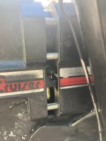
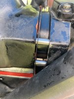
No matter which way I orient my outdrive driveshaft, I can not get the outdrive to fully seat onto the bell housing studs. It is hanging up on something near the end of its travel into the transom. I have the shift linkage on the outdrive turned clockwise and the prop shaft locked in place. The shift linkage on the bell housing side is sliding smoothly into the designated slot in the outdrive. I am thinking it must have something to do with the splines at the end of the shaft. I will attach pictures of exactly how far the installation goes before hanging up.

Does anyone have any experience or advice regarding this issue?
 

Attachments

  • IMG_4552.jpg
    IMG_4552.jpg
    1.9 MB · Views: 7
  • IMG_4553.jpg
    IMG_4553.jpg
    1.7 MB · Views: 7

Bondo

Moderator
Staff member
Joined
Apr 17, 2002
Messages
70,958
I am restoring a 1986 Cheetah 176 speedboat. It is equipped with a 3.7L Mercruiser inboard engine and an Alpha One Gen 1 outdrive. I had the outdrive removed for water impeller service as well as a gimbal bearing / bellows replacement. Despite being a huge pain, these jobs were successfully completed. I am now at the final step of re-installing the outdrive back into the bell housing / into the engine driveshaft slot.

No matter which way I orient my outdrive driveshaft, I can not get the outdrive to fully seat onto the bell housing studs. It is hanging up on something near the end of its travel into the transom. I have the shift linkage on the outdrive turned clockwise and the prop shaft locked in place. The shift linkage on the bell housing side is sliding smoothly into the designated slot in the outdrive. I am thinking it must have something to do with the splines at the end of the shaft. I will attach pictures of exactly how far the installation goes before hanging up.

Does anyone have any experience or advice regarding this issue?
Ayuh,..... Welcome Aboard,.... Did you do the alignment at the end of this work,..??
 

ThomW

Chief Petty Officer
Joined
Aug 8, 2016
Messages
615
I agree with Bondo to make sure alignment was done prior to installing.

Are both the lower unit and the control set in forward gear?
If so, while trying to get it installed the last few inches, try carefully turning the prop a little bit in a clockwise direction. That will turn the splines on the shaft and may help you have them align with the teeth in the bell housing.
 

alpacaox

Cadet
Joined
Apr 24, 2023
Messages
10
I agree with Bondo to make sure alignment was done prior to installing.

Are both the lower unit and the control set in forward gear?
If so, while trying to get it installed the last few inches, try carefully turning the prop a little bit in a clockwise direction. That will turn the splines on the shaft and may help you have them align with the teeth in the bell housing.
Ayuh,..... Welcome Aboard,.... Did you do the alignment at the end of this work,..??
Thanks for the quick replies!

I checked it once when I removed the drive, but I will verify again. To be clear, I am looking for full insertion of the alignment tool and clear spline marks imprinted all the way around the end of the tool upon removal?
 

Bondo

Moderator
Staff member
Joined
Apr 17, 2002
Messages
70,958
Thanks for the quick replies!

I checked it once when I removed the drive, but I will verify again. To be clear, I am looking for full insertion of the alignment tool and clear spline marks imprinted all the way around the end of the tool upon removal?
Ayuh,..... Correct, or damn close,....

You changed the gimbel bearing after you pulled the drive, so it Does need alignin',....
 

Scott06

Admiral
Joined
Apr 20, 2014
Messages
6,450
Thanks for the quick replies!

I checked it once when I removed the drive, but I will verify again. To be clear, I am looking for full insertion of the alignment tool and clear spline marks imprinted all the way around the end of the tool upon removal?
Yes on the grease witness marks

Also forward gear for both controller and drive. You need to hold the prop CCW with a bungee etc to keep it locked in gear. You are turning the drive so it meshes with the splines on the coupler ?
 

alpacaox

Cadet
Joined
Apr 24, 2023
Messages
10
Ayuh,..... Correct, or damn close,....

You changed the gimbel bearing after you pulled the drive, so it Does need alignin',....
I had not realized that this would change the alignment! Makes sense.
Yes on the grease witness marks

Also forward gear for both controller and drive. You need to hold the prop CCW with a bungee etc to keep it locked in gear. You are turning the drive so it meshes with the splines on the coupler ?
Yes, controller and drive in forward. I was not spinning the prop for fear that unlocking it would screw up the gear positioning. I will give this a shot after I align. I'll get on this after work and report back. Thank you two :)
 

Scott06

Admiral
Joined
Apr 20, 2014
Messages
6,450
I had not realized that this would change the alignment! Makes sense.

Yes, controller and drive in forward. I was not spinning the prop for fear that unlocking it would screw up the gear positioning. I will give this a shot after I align. I'll get on this after work and report back. Thank you two :)
You can only spin the prop CCW when in forward otherwise it will drop out of gear that way u can line up the splines
 

alpacaox

Cadet
Joined
Apr 24, 2023
Messages
10
You can only spin the prop CCW when in forward otherwise it will drop out of gear that way u can line up the splines
OK great, that is how mine functions.

I just inserted my alignment tool with a hefty dose of grease. Splines were clearly visible on the top of the tool, however, the bottom showed much less spline-age.

I guess that this means my engine is seated too low? Current plan of attack is to add spacers to the engine mounting hardware to raise the engine slightly. Is this ill advised?

How the hell does anyone lift the engine up to complete this operation?
 

alpacaox

Cadet
Joined
Apr 24, 2023
Messages
10
OK great, that is how mine functions.

I just inserted my alignment tool with a hefty dose of grease. Splines were clearly visible on the top of the tool, however, the bottom showed much less spline-age.

I guess that this means my engine is seated too low? Current plan of attack is to add spacers to the engine mounting hardware to raise the engine slightly. Is this ill advised?

How the hell does anyone lift the engine up to complete this operation?
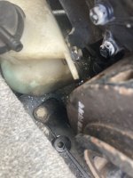
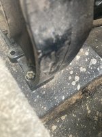
For reference, this is what my engine mounting hardware looks like. Seems like it's just 2 bolts in the bilge closest to the front of the boat.
 

Attachments

  • IMG_4562.jpeg
    IMG_4562.jpeg
    1.7 MB · Views: 5
  • IMG_4564.jpeg
    IMG_4564.jpeg
    2.2 MB · Views: 5

Scott06

Admiral
Joined
Apr 20, 2014
Messages
6,450
OK great, that is how mine functions.

I just inserted my alignment tool with a hefty dose of grease. Splines were clearly visible on the top of the tool, however, the bottom showed much less spline-age.

I guess that this means my engine is seated too low? Current plan of attack is to add spacers to the engine mounting hardware to raise the engine slightly. Is this ill advised?

How the hell does anyone lift the engine up to complete this operation?
You move the front of the engine up or down on the threaded mount on front of engine. Raise it up to get more grease on bottom side of alignment bar.

#13 in the attached link is the adjustment stud


alpacaox

Cadet
Joined
Apr 24, 2023
Messages
10

aidanmurphy

Petty Officer 2nd Class
Joined
Apr 2, 2022
Messages
101
Take a hammer with the alignment tool fully installed and tap it in the direction you need to go. The gimbal bearing has some extent of "gimbal" to it and you need to set it after install. You should not need to adjust your engine
 

alpacaox

Cadet
Joined
Apr 24, 2023
Messages
10
Quick update in case it may help someone in the future...

The engine alignment was fine! I had purchased a gasket kit from Amazon.com for this job, and the o-rings that seat around the outdrive's shaft were blocking the shaft from fully installing into the engine. I replaced them with Quicksilver brand o-rings, and the outdrive was able to be successfully installed.
 

Scott06

Admiral
Joined
Apr 20, 2014
Messages
6,450
Quick update in case it may help someone in the future...

The engine alignment was fine! I had purchased a gasket kit from Amazon.com for this job, and the o-rings that seat around the outdrive's shaft were blocking the shaft from fully installing into the engine. I replaced them with Quicksilver brand o-rings, and the outdrive was able to be successfully installed.
Thanks for closing this out. Unfortunately you see this a lot that aftermarket components dont fit correctly.
 
Top