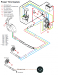
Hello all first post! I have a new to me 1991 Mercruiser 5.0L with a alpha 1 drive. The trim is not working up or down from the commander switches. No clicking. I jumped the trim solenoids at the green and blue wires and the trim goes up and down. The trim limit switch wires are frayed, can I connect these together to bypass? I pulled the switch apart on throttle (commander switch) and am getting about 1 volt at the red wire. I traced that back to a 3 prong connector near the solenoids/pump and am getting 1 volt at what I believe is the red wire there as well. Any ideas on where I should look next? I'm terrible with electrical terms and tests but have a voltmeter and need to learn. thanks

- Shop
-
Main Menu Find The Right Fit
-
-
Slide Anchor Box Anchors Shop Now

-
Back Fishing
-
View All
- Fishing Rods
- Fishing Reels
- Fishing Rod & Reel Combos
- Fishing Tools & Tackle Boxes
- Fishing Line
- Fly Fishing
- Fishing Bait & Fishing Lures
- Fishing Rod Holders & Storage Racks
- Fish Finders, Sounders & Sonar
- Trolling Motors
- Fishing Nets
- Fishing Downriggers & Acessories
- Fishing Outriggers & Acessories
- Fishing Kayaks
- Fish Cleaning Tables
-
-
Minn Kota Riptide Terrova 80 Trolling Motor w/i-Pilot & Bluetooth Shop Trolling Motors

-
SportsStuff Great Big Marble Shop Tubes

-
Big Jon Honda 5hp Outboard Shop Outboards

-
Lexington High Back Reclining Helm Seat Shop Helm Seats

-
Kuuma Stow n Go BBQ Shop Now

-
Slide Anchor Box Anchors Shop Now

-
Back Electrical
-
View All
- Boat Wiring & Cable
- Marine Batteries & Accessories
- Marine DC Power Plugs & Sockets
- Marine Electrical Meters
- Boat Lights
- Marine Electrical Panels & Circuit Breakers
- Power Packs & Jump Starters
- Marine Solar Power Accessories
- Marine Electrical Terminals
- Marine Fuse Blocks & Terminal Blocks
- Marine Switches
- Shore Power & AC Distribution
-
-
ProMariner ProNautic Battery Charger Shop Marine Battery Chargers

-
Lowrance Hook2-4 GPS Bullet Skimmer Shop GPS Chartplotter and Fish Finder Combo

-
Boston Whaler, 1972-1993, Boat Gel Coat - Spectrum Color Find your boats Gel Coat Match

-
Rule 1500 GPH Automatic Bilge Pump Shop Bilge Pumps

-
Back Trailering
-
SeaSense Trailer Winch Shop Trailer Winches

-
Seadog Stainless Steel Cup Holder Shop Drink Holders

-
Slide Anchor Box Anchors Shop Now

-
- Boats for Sale
- Community
-


