2006 Johnson 9.9 four stroke J10EL4SD…

ryanp1227

Petty Officer 3rd Class
Joined
Apr 17, 2022
Messages
78
Picked one up used for $220. Runs, but is missing some pieces. I will be running a Trollmaster throttle and panther electro steer setup, so I will have no remote controls. Would like to know if I can simply wire in a push button start switch and disregard the remaining wires in the harness?

Also does ANYONE have a proper wire color code guide for this thing? It seems to be a little different than what I can find online. Would it use the Johnson/Evinrude colors or the Suzuki colors, since it was made by Suzuki for Johnson? From what I can tell, the harness wires are as follows:
Blue - oil pressure switch
Blue/Red - engine stop switch
Black - ground
Brown - neutral switch
White - rectifier/power
Yellow/Black - CDI unit (?)

Any help is appreciated
 

ryanp1227

Petty Officer 3rd Class
Joined
Apr 17, 2022
Messages
78
Need to bump for possible help. I can find Johnson/Evinrude color codes, but im pretty sure the witing with this is different. Doesnt match what I can find of suzuki either
 

ryanp1227

Petty Officer 3rd Class
Joined
Apr 17, 2022
Messages
78
I wouldnt be asking if I hadnt scoured the manual first. What I posted above are the wires I have identified by reading each section. There is no schematic that shows what every wire goes to. After that I checked ONLINE and it doesnt seem the standard Johnson/Evinrude wiring codes match up. Suzuki either.
 

saltchuckmatt

Commander
Joined
Jul 19, 2019
Messages
2,663
Well a few questions, so your motor was not a tiller motor right? It had a remote and you really don't need it?

This motor has a charging system correct? Will you be using that? Seems like more of a kicker motor.

I think I can piece what wires should work for you.
 

ryanp1227

Petty Officer 3rd Class
Joined
Apr 17, 2022
Messages
78
So this is an electric start remote model. I do not have the controls, harness, ignition switch, emergency stop switch, or throttle cables. I pieced together the parts needed to shift it like you would the tiller models. It will be used as a kicker/trolling motor. It has a charging system. I have wireless electronic steering and throttle. I will eventually find what is needed to correctly hook up a tiller handle, but thats for later.

What I need to do is connect the ignition and emergency stop. I may use a key ignition, but more than likely will be using an OEM switch assembly. From what I can tell, the ignition will use the white and brown leads only, and the stop switch/lanyard will use the blue w/red tracer and black leads only. The primer is automatic. Connected in that way, once the power and ground are connected, should start this thing, right?
 

saltchuckmatt

Commander
Joined
Jul 19, 2019
Messages
2,663
Ok, might not be the best person here but let me get you started and others will chime in.

First a few questions. The wire colors you stated above are on the motor side rubber plug that goes to a remote harness, right?

Let's list what you need. You can install a momentary start button on the engine. Typically it will have fused battery power to one side and the other side goes to the activation side of the starter soleniod. Check to see if any of those wires are hot when you hook it to the battery otherwise make your own. Pretty sure nutruel brown wire grounds the soloniod so it will activate. Is the soloniod mounted in rubber? I think the motor will run without the remote (no ignition) but you will need to be able to shut it off. By a man overboard/kill switch and mount it on the engine. One wire to ground and one wire to....not sure here, typically power pack.

Primer typically needs juice to activate so not sure why you said it automatic. You may need a key switch which should help on a few of these things otherwise another moment switch will have to be installed. Low oil I'm not sure....charge wire is typically red coming from the rectifier and goes to the batter hot on the solenoid.

Sorry, I know older two strokes better but I think this could get you started. I will investigate more and I'm sure more will chime in telling me how wrong I am...Lol
 

saltchuckmatt

Commander
Joined
Jul 19, 2019
Messages
2,663
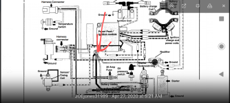
Here is another with similar issue. Look at the wiring scem. Not in color but is this what your book shows?


ryanp1227

Petty Officer 3rd Class
Joined
Apr 17, 2022
Messages
78
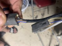
Engine side of the harness.
Here is another with similar issue. Look at the wiring scem. Not in color but is this what your book shows?

Doesnt help much, and that is definitely not in my service manual. It shows the harness with like 10+ leads going in from engine side. My harness only has 7 between the two connectors.
 

saltchuckmatt

Commander
Joined
Jul 19, 2019
Messages
2,663
Okay, well without a remote you will have to adlib some kind of harness, does your engine have a common lug lime this where all your hots go to? Understanding this is half or more of your battle.
 

Attachments

  • Screenshot_20230204-175828~2.png
    Screenshot_20230204-175828~2.png
    884.5 KB · Views: 3

ryanp1227

Petty Officer 3rd Class
Joined
Apr 17, 2022
Messages
78
Ok, might not be the best person here but let me get you started and others will chime in.

First a few questions. The wire colors you stated above are on the motor side rubber plug that goes to a remote harness, right?

Let's list what you need. You can install a momentary start button on the engine. Typically it will have fused battery power to one side and the other side goes to the activation side of the starter soleniod. Check to see if any of those wires are hot when you hook it to the battery otherwise make your own. Pretty sure nutruel brown wire grounds the soloniod so it will activate. Is the soloniod mounted in rubber? I think the motor will run without the remote (no ignition) but you will need to be able to shut it off. By a man overboard/kill switch and mount it on the engine. One wire to ground and one wire to....not sure here, typically power pack.

Primer typically needs juice to activate so not sure why you said it automatic. You may need a key switch which should help on a few of these things otherwise another moment switch will have to be installed. Low oil I'm not sure....charge wire is typically red coming from the rectifier and goes to the batter hot on the solenoid.

Sorry, I know older two strokes better but I think this could get you started. I will investigate more and I'm sure more will chime in telling me how wrong I am...Lol
Auto enricher, not primer. Either way, nothing to do with turning on/off
 

ryanp1227

Petty Officer 3rd Class
Joined
Apr 17, 2022
Messages
78
Okay, well without a remote you will have to adlib some kind of harness, does your engine have a common lug lime this where all your hots go to? Understanding this is half or more of your battle.
My plan is to rig a new harness using only the wires I need to start and stop the motor. I have the connectors and the parts, just need to make sure the connections will be correct.
 

saltchuckmatt

Commander
Joined
Jul 19, 2019
Messages
2,663
My plan is to rig a new harness using only the wires I need to start and stop the motor. I have the connectors and the parts, just need to make sure the connections will be correct.
Yes, I get it... probably should hook the low oil cut out in as well.
 

saltchuckmatt

Commander
Joined
Jul 19, 2019
Messages
2,663
Tap my picture and look, rectifier should go to hot and you can see how the starter wires go....just need to wire in a switch to activate it.

So that starts it and gives you the charge wire.

Do you have any pictures of the motor showing wires, starter and such?
 

ryanp1227

Petty Officer 3rd Class
Joined
Apr 17, 2022
Messages
78
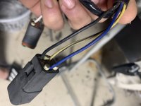
These are the two that connect to the remote side harness. One is Black, Brown, Blue/Red, and White. The other is Blue, Yellow/Black, and Black.
 

Attachments

  • 53C793E6-011F-477E-BDBD-79D85981D321.jpeg
    53C793E6-011F-477E-BDBD-79D85981D321.jpeg
    884.7 KB · Views: 3
  • E8F11854-EFD1-4391-9ABD-49F91C069139.jpeg
    E8F11854-EFD1-4391-9ABD-49F91C069139.jpeg
    930.4 KB · Views: 3

ryanp1227

Petty Officer 3rd Class
Joined
Apr 17, 2022
Messages
78
Tap my picture and look, rectifier should go to hot and you can see how the starter wires go....just need to wire in a switch to activate it.

So that starts it and gives you the charge wire.

Do you have any pictures of the motor showing wires, starter and such?
What I THINK I need is Blue/Red & Black for the lanyard stop switch, and White & Brown for the start button. White I believe ends up at the rectifier, brown to neutral safety
 

ryanp1227

Petty Officer 3rd Class
Joined
Apr 17, 2022
Messages
78
Yellow w/Black tracer goes to CDI…Tach lead maybe? If so, not using it
 

saltchuckmatt

Commander
Joined
Jul 19, 2019
Messages
2,663
Typically omc tach lead was brown so right now the colors aren't even jiving with me.

I don't need wire end pictures I need pictures showing where the wires go to and then I might be able to make sense of it.
 

ryanp1227

Petty Officer 3rd Class
Joined
Apr 17, 2022
Messages
78
Brown is definitely to the neutral safety switch.

White (actually White w/Red tracer) definitely ends up at the rectifier.

Blue definitely goes to the oil pressure switch

Yellow w/Black tracer is definitely looping back to the CDI box

Black is ground.

So that leaves this Blue w/Red tracer.
 
Top