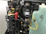
1998 Mercury 125 2+2 not charging batteries

williamtii

Cadet
Joined
Jun 20, 2017
Messages
15
Hi Everyone,

I am having trouble figuring out why the batteries are not charging on a Mercury 125hp 2+2 from around 1998. The serial number sticker is gone but from buying (and returning) parts 1998 is our best guess.

It starts, runs, and drives just fine but is not charging the batteries so after a 4hr fishing trip with multiple stop/starts they go dead. It has 2 batteries which are about 4 months old.

After doing some research a got a new Voltage Regulator and an eBay Stator which tested good on the bench (620ohms) per the figures in the link below. (40-125hp Green + White wires). I do not have the DVA leads but assume its making power since it runs fine

https://www.outboardignition.com/page39.asp

When replacing the parts I noticed the connections from Stator the Voltage regulator were pretty crusty. One broke off easily instead of unplugging so I figured I was on the right track. I replaced the bad wiring and loosened, cleaned, tightened every connection I could see.

Unfortunately the batteries are still not charging! I checked the voltage from the Regulator to the Solenoid (red wire) while running well above idle and it showed battery voltage. No changes in voltage throughout the rev range.

The only thing I notice is that I am missing approx 250-500rpm's off the top end. The Tach does not work so I am using the less than precise loud-o-meter.

Any ideas on what to check next? I would like to know it's running well before pulling it for the Winter. Thanks!
 

merc850

Commander
Joined
Jul 7, 2010
Messages
2,046
It will start and run because the ignition is alternator driven and the batteries are just for starting. What kind of batteries are you using? Is the motor charging them both at the same time?
You should only charge 1 battery with the motor and not a deep cycle one; a regular marine starting battery is called for.
I checked the voltage from the Regulator to the Solenoid (red wire) Should be + to - to see if it's charging.
It sounds like the stator that produces AC voltage is damaged again.
 

williamtii

Cadet
Joined
Jun 20, 2017
Messages
15
Thanks, looks like you are onto something. Both batteries are the same, these from Autozone.

https://www.autozone.com/exterior-a...battery-12-months-free-replacement/298374_0_0

We have a switch on the stern that allows you to select battery 1, 2, All, and Off. In the 8 years we have had it we always use All for operations.

From your post it looks like we should be using a starting battery for normal operations as battery #1 and a deep cycle as battery #2 if the engine is off. Correct yes?

I am happy to swap batteries but am a bit confused since we have been running this setup for 8 seasons now, replacing the batteries every 2-3yrs as a precaution more than anything.

​​​​​​​FYI I have a new meter with DVA Leads on the way so should have some more info this week. Thanks for the good advice so far.
 

merc850

Commander
Joined
Jul 7, 2010
Messages
2,046
A starting battery is designed for short high draw periods whereas a deep cycle is for long constant draws; then charging.
A friend of mine used a deep cycle battery for start and stereo and he always charged it before he went out; his alternator didn't work so he used a 40 amp charger and that took 1/2 hr. I think the battery killed his stator.
You could use use the switch as you described (1 start 2 deep) but you'll have to run the motor for a while on 1 then switch to 2.
The tach not working could be due to stator problems - check a wiring diagram to see where the tach gets its signal from and check the switch for continuity; is it a marine switch like "Perko" makes. You can also install a voltmeter that will show you the charging/battery condition.
 
Last edited:

williamtii

Cadet
Joined
Jun 20, 2017
Messages
15
OK so I have a new fancy Fluke meter and DVA leads courtesy of Amazons Black Friday sale.

One good piece of news is that when I went to do more testing the tachometer magically works again. Im Guessing that by cleaning up connections and plugging/unplugging things it regained connection.

The battery switch is a Perko, cleaned up the connections there too. I will address the battery mismatch in the spring, just trying to make sure the Stator/Regulator issue is resolved before putting it away. Would I be better off with 2 starting batteries? Or a Starting and a deep cycle? Its a 22ft fishing boat without much electronics, just the fish finder and nav lights.

So here is what I found, using the following guide from CDI. Both batteries fully charged, but using one only for testing.

http://www.outboardmarine.co.nz/catalogues/battery-differences.pdf

+++++++++++++++++++++++++++++++++++++++++++++++++++++++++++++++++++++++++++++++++++++++++

Section 1. Regulator / Rectifier tests
1. Yellow wires both give 0.2V DVA when running at 1500rpm (Fail)
2. This I am unsure of as the Yellow Battery Charge Wires are Positive (A/C) and Red Wires to the Solenoid are positive (D/C) How will two positive leads give a reading?
3. N/A
4. Grey Wire gives 0.2V (Fail) but the tach works?

Section 2 Rectifier/Regulator Bench Test
1. Red>Yel = 0.176V /// Yel > Red = 1.652V. Per the guide I am supposed to get a reading one way but not the other. I tested the old one at home and got 0.44V one way and OL or open the other. Not sure what to make of this since it looks like the old one is good and the new one is not. I have another better quality (AKA more expensive) one on the way.

Testing the resistance of the wires to ground showed 2.6M ohms for Yellow Wires and 46M ohms for red.

2. Grey wire to ground read 4M ohms - Grey>Red was 46.2M ohms and Grey>Yel was 2.8M ohms

Tachometer Test - 0.2V as mentioned above, but tach works?

+++++++++++++++++++++++++++++++++++++++++++++++++++++++++++++++++++++++++++++++++++++++++=

I also tried putting the old Stator back on and got 0.2 DVA or less from each yellow wire. I am thinking the new to me eBay Stator was not working from the start, and it fried the voltage regulator.I am not positive though since the regulator test results are somewhat inconclusive. Both Stators bench test fine between the Gr/Wht and Wht/Gr wires, between 600-700ohms.

Should I just go ahead and pick up a new stator since neither are sending voltage to the regulator? Or am I missing something?

One thing I did find odd is that the new regulator came with bullet connections for each separate wire. The old regulator had the Yellow Charge wires combined with an easy disconnect, same with the red wires to the Solenoid. Is it OK for these to be joined or should they be separate? The motor has been like this for the 8 years we have owned it so I am assuming its OK. Here's a pic to show what I am talking about:

https://i.imgur.com/dse7HwT.jpg
 

Attachments

  • photo304900.jpg
    photo304900.jpg
    2.2 MB · Views: 3

merc850

Commander
Joined
Jul 7, 2010
Messages
2,046
I don't know the specs for the components but I think you should clean the ground connection on the starter mount bolt; it might be part of the problem.
 

sam am I

Commander
Joined
Jun 26, 2013
Messages
2,169
After hooking up the DVA adapter inline, the fluke is set to read "DC"?

BTW, what is the model number of your new fluke?

Section 1. Regulator / Rectifier tests


1. Yellow wires both give 0.2V DVA when running at 1500rpm (Fail)

See "DC" setting above

2. This I am unsure of as the Yellow Battery Charge Wires are Positive (A/C) and Red Wires to the Solenoid are positive (D/C) How will two positive leads give a reading?

The two yellow AC wires in this case are neither positive or negative per-se (see transformer theory for some light evening reading tonight), when measure these, nevermind the colors and/or polarity of the DVA leads when hooking up here. Just hook one yellow to one DVA lead(red for example) and the other yellow to the other DVA lead (black for example) and refer to "DC" setting above


......

4. Grey Wire gives 0.2V (Fail) but the tach works?

Think we're having user issues again....see "DC" settings above
 
Last edited:

Faztbullet

Supreme Mariner
Joined
Mar 2, 2008
Messages
15,902
Yellow stator wires output is AC not DC...should be 15-25VAC or higher at idle. Grey output to tach is AC usually in the 1-5 VAC range at idle.
 

williamtii

Cadet
Joined
Jun 20, 2017
Messages
15
Here's the latest, first cleaned the crusty Starter Ground. The connections were good, just surface rust on the bolt head, all nice and clean now. I used a good car battery and disconnected the 2nd deep cycle for further testing.

In response to Sam am I:

- I got a Fluke 117, along with the DVA Leads.
- Meter *WAS* set to A/C for the Stator Tests, and D/C for everything downstream of the Regulator. From the manual that came with the DVA leads, the meter should have been set to D/C as you said. (User Error)

The new voltage regulator came, purchased from this site. The first one was $36 off amazon, and I see them $100 and up on other sites. Seems like a crazy swing in price and quality considering what a simple part it is. The one off this site was $60 and has MUCH better wire quality and connections.

I tried the old stator first, and got 5.5 Volts out of each wire (Fail)
Swapped it with the eBay one, 5.5 Volts again from each yellow lead (Fail)

Maybe both stators are bad, but it is suspicious that they both put out the same voltage. Could they both be good, and the problem lies elsewhere?

In other bad news the Tach is no longer working with the new Voltage Regulator :(
 

sam am I

Commander
Joined
Jun 26, 2013
Messages
2,169
In response to Sam am I:


- I got a Fluke 117, along with the DVA Leads.

Nice meter, will last you a life time...


- Meter *WAS* set to A/C for the Stator Tests, and D/C for everything downstream of the Regulator. From the manual that came with the DVA leads, the meter should have been set to D/C as you said. (User Error)

Np, common error

The new voltage regulator came, purchased from this site. The first one was $36 off amazon, and I see them $100 and up on other sites. Seems like a crazy swing in price and quality considering what a simple part it is. The one off this site was $60 and has MUCH better wire quality and connections.

Well the design is actually fairly complicated internally BUT, been around forever and is no way worth paying more than $30/40 ea. for even a high quality unit......The Chinese have driven some very greedy ppl's prices down quite nicely and to fair market value I might add and also IMO.

I tried the old stator first, and got 5.5 Volts out of each wire (Fail)
Swapped it with the eBay one, 5.5 Volts again from each yellow lead (Fail)

Something doesn't sound right, you said "each wire"? The yellow wires are isolated from ground.........Put the DVA leads ACROSS both yellow wires...fire up the motor.

Just hook one yellow to one DVA lead(red for example) and the other yellow to the other DVA lead (black for example) and refer to "DC" setting above

Maybe both stators are bad, but it is suspicious that they both put out the same voltage. Could they both be good, and the problem lies elsewhere?

Agreed, read up

In other bad news the Tach is no longer working with the new Voltage Regulator :(


Something doesn't sound right, again. The VR derives its tach sig from the stator's AC pulses, you hooked up all wires including the two yellow wires to the VR when checking the the tach right?
 
Last edited:

sam am I

Commander
Joined
Jun 26, 2013
Messages
2,169
Yellow stator wires output is AC not DC...should be 15-25VAC or higher at idle. Grey output to tach is AC usually in the 1-5 VAC range at idle.

Meter has to be set on DC to read AC sig's through DVA adapter.......OP reports/is using his new meter with his new DVA adapter inline. I think the fluke 117's BW could measure it however but, of course he'd have to remove the inline DVA, switch his meter to AC and then measure across the yellow leads.....Same with Tach, remove the DVA first though then switch to AC.
 
Last edited:

williamtii

Cadet
Joined
Jun 20, 2017
Messages
15
"Something doesn't sound right, you said "each wire"? The yellow wires are isolated from ground.........Put the DVA leads ACROSS both yellow wires...fire up the motor."

- Yes I was testing each wire while plugged in and running at approx 1500rpm. Red lead to Stator Wire and Black lead to ground. This from the first step test for the Regulator in the CDI Troubleshooting Guide.
I did not test across the Yellow Stator leads, I missed that wording and thought it was the same test! Will try that next.

"Something doesn't sound right, again. The VR derives its tach sig from the stator's AC pulses, you hooked up all wires including the two yellow wires to the VR when checking the the tach right?"

-Yes, everything all hooked up, DVA was reading approx 11V but nothing on the tach. I did not spend much time here since I am used to not having a tach. I will try again when testing the Stator and revert. Thanks for the help so far, it's coming out of the water Sunday so I'm running out of time!
 

sam am I

Commander
Joined
Jun 26, 2013
Messages
2,169
- Yes I was testing each wire while plugged in and running at approx 1500rpm. Red lead to Stator Wire and Black lead to ground. This from the first step test for the Regulator in the CDI Troubleshooting Guide.
I did not test across the Yellow Stator leads, I missed that wording and thought it was the same test! Will try that next.

CDI is wrong if they claim you should get a reading from either yellow wire to ground on this stator (and/or your reading some other testing procedure not for your stator and/or you're mis-interpreting what CDI says here for your stator ).

The stators two yellow charge wires are 100% isolated from the boats ground. You;ll never get an accurate reading measuring either yellow wire to ground, only across the two............

Part of the procedure is to actually check this with an ohm meter by measuring the/each yellow wire to ground (metal body of stator). The readings are suppose to be in the Meg (millions of) ohms. e.g., the yellow wire are NOT electrically not connected to ground.

Below is directly from Merc for your motor's stator. See second row, second column....."No continuity" when reading "Between either yellow stator lead and engine ground"


Click image for larger version  Name:	Mercury Service Manual for 75--90-100-115-125 hp.jpg Views:	1 Size:	49.1 KB ID:	10686250

-Yes, everything all hooked up, DVA was reading approx 11V but nothing on the tach. I did not spend much time here since I am used to not having a tach. I will try again when testing the Stator and revert. Thanks for the help so far, it's coming out of the water Sunday so I'm running out of time!

11V sounds about right.........Recall this is a peak reading where the AC (or DC pulsed or DC) signal's peak value charges a capacitor and is then temporally held on the dva's capacitor? This tells me (us) you are getting signal pulses that are approx 11V peak (or 11 Vdva). Not sure why the tach quit but, sounds like it's getting its signal out of the rec/reg. Assume this was on the rec/reg's gray wire?

Also recall that tach signal (11 Vdva) is derived from the stators charge windings? This is good news, you're stator is working!!

Thinking your problem/s lay somewhere else........as your trouble shooting/info isn't too accurate and is leading off down the wrong $path$, nothing personal but, I suggest a marine mech at this point.
 
Last edited:

sam am I

Commander
Joined
Jun 26, 2013
Messages
2,169
CDI is wrong if they claim you should get a reading from either yellow wire to ground on this stator (and/or your reading some other testing procedure not for your stator and/or you're mis-interpreting what CDI says here for your stator ).

when I say "reading" here, In this case, I'm referring to a voltage (DVA and/or AC) reading NOT resistance.

The stators two yellow charge wires are 100% isolated from the boats ground. You;ll never get an accurate reading measuring either yellow wire to ground, only across the two............


when I say "reading" here, In this case, I'm referring to a voltage (DVA and/or AC) reading NOT resistance.
 
Top