Yamaha 2005 F90 TLRD High Idle

Joined
Aug 2, 2020
Messages
7
This started off intermittent. Long runs at WOT and when pulled back to idle RPM’s were 1200 at first. A coupe of times it went 2500-2800. Turning off and waiting for restart and it would be good for until WOT again. I checked wires to ISC and found the green/black didn’t have continuity. Repaired that.

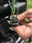
This is no longer intermittent. It does it all the time now at start up. I was thinking back through attempts to trouble shoot. When I was looking for loose or distressed wire I was jiggling the harness near the ISC. I reached down and bumped the throttle arm up a bit and it took off up to 2800 and has stayed in that range since. Throttle valve is not loose or missing screws. TPS voltage is in range for idle. Placing my finger over the inlet for the ISC kills the motor. If I take it easy when I put my finger over the valve I can get it to idle at 400 or so. So it’s not leaking air any where else.


I have posted this elsewhere and I’m pasting where I’m at now. I have replaced the ISC valve and installed a used ECM. No changes to below after.

“1100 rpm for a few seconds, ramps up to 2500-2800. Clearly sucking air in the ISC valve.

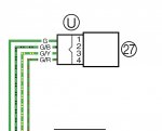
Engine off key on voltage at ISC connector
G/y. 12.47
G/b 8.53
G/r 8.44
Same voltages when tested at green ISC connector wire and engine ground

Engine running
G/y 14.62
G/b 8.65
G/r 8.56

Execute stationary test of ISC and I can hear it doing it’s thing.

Execute ISC valve 100% open in active test. Engine running in neutral at 2800, As it increases in % open the ISC actually closes and eventually kills the engine at 100% open. Obviously activating in reverse.......

Check voltage at ISC connector during ISC valve active test and voltage drops to
G/y drops to 7.5
G/b drops to 7.26
G/r drops to 7.24

Disconnect ISC valve and engine will idle at 1100 all day long. Of course I’m not sure what all this means other than the ISC valve appears to be working in reverse”
 

rejesterd

Petty Officer 2nd Class
Joined
Sep 20, 2018
Messages
142
Tough one..

I'm wondering if you have an issue with the engine grounds. Where are you holding your test probes when you take those voltage readings? I might be able to tell you what my numbers are this weekend, just so you have a reference point. I have the F50, but it's a very similar design. I've never checked mine, but like I said in the other forum, 7.something or 8.something volts certainly doesn't sound right. I would think at least one of those 3 wires should show zero volts.

And again, the timing info from your YDIS report (on the other forum) looks strange to me. When idling, mine will always give a value like "ATDC 10,deg" or "ATDC 11,deg". Did you end up checking the voltage on other components like the MAP sensor or the TPS? For those, you should get 5V on the orange wire.
 
Joined
Aug 2, 2020
Messages
7
I tried the new/used ECM briefly and didn’t record any data. I did see what you would expect to see for timing in YDS for the brief time I ran it. I can check more this afternoon.

TPS voltage known is only what YDS is telling me. I did try to adjust it down closer to the .5v at the low end of spec. At 1200 RPM it’s was .912 as I recall. Spec is .8-1.2v

I have visually checked grounds, but maybe I should dig deeper. I don’t have a bunch of corrosion under the cowling. It is odd to me that bumping the throttle arm made the idle jump so high and I probably shouldn’t over look that. Everything seams to be in order on linkage adjustment, but it might be worth a shot. The throttle arm is down on the stop.

I just pulled an all nighter at work and I’ll check some things out this afternoon.

Thanks for the help.

edit to add readings were taken at connector green and engine ground for ISC voltages. No change.
 
Last edited:

rejesterd

Petty Officer 2nd Class
Joined
Sep 20, 2018
Messages
142
For the TPS, I'm talking about the reference voltage (not what YDIS reports). That should always be 5V on the orange wire. Same for the MAP sensor (aka the "sensor assembly").

Might be worth going through the linkage procedure from the manual, visually inspect the throttle body to make sure nothing is bent, and removing/reinstalling the TPS. The TPS might just be loose.

It's hard to imagine this only being related to linkage, given the odd behavior of the ISC during the active YDIS test. But I'm sure you've gone over the wiring more than once at this point.
 

rejesterd

Petty Officer 2nd Class
Joined
Sep 20, 2018
Messages
142
Oh, and here's another thing from your YDIS report that I totally forgot about..

Intake temperature (below 158) 105.8 °F
Intake pressure 11.57 inHg (at 2700 rpm)

If you hook up YDIS in the morning and just turn the key to ON, how does the intake temp reading compare to your local weather station? The two shouldn't be more than 9F off from each other. If you're in a hot climate, then 105.8F might be ok, but I would at least check it cold in the morning.

Also, an intake pressure of 11.57 while the engine is running at ~2800 rpm seems wrong to me. If the engine was actually idling at 750-800, then 11.57 would be ok.. but your values seem too low for the corresponding rpm values that were logged. So this again, points to something wrong with the 5V reference circuit that includes the TPS and MAP sensor.
 
Joined
Aug 2, 2020
Messages
7
For the TPS, I'm talking about the reference voltage (not what YDIS reports). That should always be 5V on the orange wire. Same for the MAP sensor (aka the "sensor assembly").

Might be worth going through the linkage procedure from the manual, visually inspect the throttle body to make sure nothing is bent, and removing/reinstalling the TPS. The TPS might just be loose.

It's hard to imagine this only being related to linkage, given the odd behavior of the ISC during the active YDIS test. But I'm sure you've gone over the wiring more than once at this point.

Reference voltage for MAP and TPS both is 5.02v. I took the TPS off. Exercised it a few times and put it back on. I indexed it and put it on in the same place. Didn't check voltage range. Interestingly when I started it, the motor idled at 800 for a few seconds instead of the 1100 I have been seeing and then only ramped up to 2400 instead of the 2500-2800.

Nothing bent on the TB and linkage.

And thanks again for helping out!!
 

rejesterd

Petty Officer 2nd Class
Joined
Sep 20, 2018
Messages
142
Just make sure to check the 5V reference while the engine idles (not just at key-on). And check the intake temp cold in the morning to make sure it's not too far off. If it's more than 9F off, that might explain the behavior (and also the codes 29 and 37). Speaking of the codes, I would clear the code 29 and see if it comes back. YDIS can conjure up many red herrings, but it's worth verifying that the code isn't reoccurring, the MAP and TPS sensors get 5V reference while idling, and it's actually reporting at least a semi-correct temperature in the morning.

800 is better to start with, but when it jumps up after a few seconds like that, to me, there's only one reason why that could happen: the ISC is opening too much. Aside from something weird going on with the wiring or inside the ECM itself, the reason for that has to be a bad sensor (TPS, MAP, or pulser coil).

Yet, your YDIS report showed that the ECM requested that it only open 10%.. given what the actual engine speed is, it has to be opening way more than that. So how could the engine be idling way too high while the ECM is only requesting the ISC open to 10%? The only answer I have for that would be a stuck open ISC (so the engine idle speed is way too high, and the ECM detects this and tries to close off the ISC almost completely) or the wiring is in fact bad. But again, you replaced it, so it seems something else is amiss. Do you actually hear the ISC rattle when you turn off the engine?

Might be good to collect a new YDIS report to compare it to the previous one.
 
Last edited:
Joined
Aug 2, 2020
Messages
7
I think I found it. Someone questioned if I had taken a photo of the wiring at ISC connector. I repaired a broken wire by de-pinning connector. After that repair the idle was still high. I de-pinned all wires and confirmed good connections and reassemble FOLLOWING my service manual. Subsequent to rewiring connector I installed a new ISC valve. Well, my photo of the connector doesn’t match the manual. I ran it for 2-3 minutes idling at 700.
 

Attachments

  • photo336934.jpg
    photo336934.jpg
    242.4 KB · Views: 0
  • photo336935.jpg
    photo336935.jpg
    1.9 MB · Views: 0

rejesterd

Petty Officer 2nd Class
Joined
Sep 20, 2018
Messages
142
Nice. I'm curious as to what the voltages are now on those wires.
 
Joined
Aug 2, 2020
Messages
7
Voltage was the same when testing at the connector. I didn't check while running. I would have to back probe the connector and to be honest having had one apart I know it would be tough to get a probe on the pin. The wires run through a rubber boot that are crimped to the hoop at the end of the pin. Of note, the connector is a common 4 wire denso alternator connector. Toyota, Nissan etc.

https://www.amazon.com/gp/product/B014Z7FFL2/ref=ppx_yo_dt_b_asin_title_o00_s00?ie=UTF8&psc=1

Ran it for 30 minutes on the muffs. Only ran it up to 2000 RPM. When up to operating temp the tach was bouncing between 600-700. Spec is 700 +/- 50. So I think I'm good.
 

rejesterd

Petty Officer 2nd Class
Joined
Sep 20, 2018
Messages
142
Good to know, thanks. Surprising, but now I won't suspect my ISC is a problem if I get similar voltage numbers. There's not a lot of info from Yamaha about the ISC out there.

Yeah, I would say 700 is close enough.
 
Joined
Aug 2, 2020
Messages
7
Good to know, thanks. Surprising, but now I won't suspect my ISC is a problem if I get similar voltage numbers. There's not a lot of info from Yamaha about the ISC out there.

Yeah, I would say 700 is close enough.

Just thinking out load here. I believe my original ISC valve was sticking, so maybe can use voltages I saw as a guide to evaluating if it’s getting the correct signal, but could still be a faulty ISC.
 
Top