Hey y'all,
First time posting, long time lurker! Asking for a bit of knowledgeable guidance.
We've got a wiring challenge with an older Bayliner Capri boat with the VP 270 outdrive w/ tilt only, no trim, and the current engine, AG125A 4 cyl. is not the original, which was the AQ125A model. It was locked up tighter than a tick, was removed and a boneyard replacement, the AG125A was located and installed.
Got the engine running after a bit and it runs great! However, we we're having an issue with getting the outdrive to raise and lower. It raised and lowered just fine before the engine swap so we're sure it's just a wiring issue of getting the right wires in the right places.
Here are our issues:
1. The mechanic that did the swap did not label any wires when the engine swap was done and due to his general incompetence, has been relieved of further involvement. So we're on our own and being fairly competent at mechanical stuff and basic wiring, we're gonna finish the job for a friend.
2. We are unsure as to what side of the coil, + or -, that the small wires go to.
The thin wires with the small ring terminals are: Red, Purple, Lt. Blue and "Lt. greyish."
( I just read in the forums here that the purple is the "ballast wire", yes? )
What wires, exactly, goes where, exactly, on the + or - terminals on the new coil?
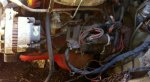
3. There is a "Mystery Wire" that we can't figure out where it goes. See pic I found on Google Images / not the motor in stalled in boat now.
It's a factory wire, 12 / 13 ga. Black, has a large, 1/2" opening ring terminal on the end, has the word "Body" printed on the terminal's shrink wrapping, comes down from the relay box, inside the thick grey covered line that also encloses the thick red wire going from the inline 20 amp fuse into the black relay box.
I have seen numerous pictures, in forums and Google Images, of this wire just hanging loose, but NEVER where it's actually hooked up to.
Here is the kicker: With ignition key on, the is just enough voltage present to have a "dim" test bulb. When the dash toggle switch (tested and is functional, has purple, brown and blue wires attached) for the outdrive is moved to the "raise or lower" position, there is more voltage there as to make the test bulb glow brightly.
This is telling me that the switch is allowing the circuit to be made and allows the drive to raise or lower.
Yet, the drive does nothing. Indicator lamp is ON, when ignition key is off and goes off when key is in accessory position.
Some information:
1. Tested the lifting motor, (2 wire model / brown and black wires) and the drive raises and lowers just fine.
2. Motor cutout switch / "end stroke limit switch" works fine, continuity tested and when pushed, breaks circuit.
3. Relay box is mounted correctly so motor cutout switch does work as intended.
4. All of the green "continuity wires" are installed.
5. Two new relays installed, one at a time, 1 wire at a time, so we're pretty sure they are wired correctly.
6. There is 12 volts+ at the relays
OK, there you have it. A bit of guidance would be most appreciated!
Also, how does one determine if our 270 outdrive is an "B, C or D" model? I read there are different ratios involved with the different designations.
First time posting, long time lurker! Asking for a bit of knowledgeable guidance.
We've got a wiring challenge with an older Bayliner Capri boat with the VP 270 outdrive w/ tilt only, no trim, and the current engine, AG125A 4 cyl. is not the original, which was the AQ125A model. It was locked up tighter than a tick, was removed and a boneyard replacement, the AG125A was located and installed.
Got the engine running after a bit and it runs great! However, we we're having an issue with getting the outdrive to raise and lower. It raised and lowered just fine before the engine swap so we're sure it's just a wiring issue of getting the right wires in the right places.
Here are our issues:
1. The mechanic that did the swap did not label any wires when the engine swap was done and due to his general incompetence, has been relieved of further involvement. So we're on our own and being fairly competent at mechanical stuff and basic wiring, we're gonna finish the job for a friend.
2. We are unsure as to what side of the coil, + or -, that the small wires go to.
The thin wires with the small ring terminals are: Red, Purple, Lt. Blue and "Lt. greyish."
( I just read in the forums here that the purple is the "ballast wire", yes? )
What wires, exactly, goes where, exactly, on the + or - terminals on the new coil?
3. There is a "Mystery Wire" that we can't figure out where it goes. See pic I found on Google Images / not the motor in stalled in boat now.
It's a factory wire, 12 / 13 ga. Black, has a large, 1/2" opening ring terminal on the end, has the word "Body" printed on the terminal's shrink wrapping, comes down from the relay box, inside the thick grey covered line that also encloses the thick red wire going from the inline 20 amp fuse into the black relay box.
I have seen numerous pictures, in forums and Google Images, of this wire just hanging loose, but NEVER where it's actually hooked up to.
Here is the kicker: With ignition key on, the is just enough voltage present to have a "dim" test bulb. When the dash toggle switch (tested and is functional, has purple, brown and blue wires attached) for the outdrive is moved to the "raise or lower" position, there is more voltage there as to make the test bulb glow brightly.
This is telling me that the switch is allowing the circuit to be made and allows the drive to raise or lower.
Yet, the drive does nothing. Indicator lamp is ON, when ignition key is off and goes off when key is in accessory position.
Some information:
1. Tested the lifting motor, (2 wire model / brown and black wires) and the drive raises and lowers just fine.
2. Motor cutout switch / "end stroke limit switch" works fine, continuity tested and when pushed, breaks circuit.
3. Relay box is mounted correctly so motor cutout switch does work as intended.
4. All of the green "continuity wires" are installed.
5. Two new relays installed, one at a time, 1 wire at a time, so we're pretty sure they are wired correctly.
6. There is 12 volts+ at the relays
OK, there you have it. A bit of guidance would be most appreciated!
Also, how does one determine if our 270 outdrive is an "B, C or D" model? I read there are different ratios involved with the different designations.