Raw water cooling question

Sea18Horse

Chief Petty Officer
Joined
Jun 1, 2008
Messages
626
Greetings all.

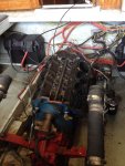
I'm in the process of restoring a 1965 Owens with a SBC inboard. I'm pulling the engine apart for some mechanical work. Head gaskets and a camshaft & lifters at the least. This engine is raw water cooled and it runs very cold. I have never seen it get above about 120 degrees F. Tonight I pulled the exhaust manifolds and risers off. They are Barr marine manifolds and risers. http://www.barrmarine.net/flagship.html

In the link they are CHV 1 83 manifold and 20 0082 riser. I was looking for new riser gaskets and noticed that the ones I currently have between my manifolds and risers are 1 0104P. These are listed for fresh water cooling. They show a 1 0107 for raw water cooling Or 1 0106P used for raw water cooling used in pre-heating applications. (Block off plate with vent holes). My question for the cognoscenti is which one would you guess is most likely to get me to a reasonably normal operating temp? My gut tells me that the wide open gasket should extract the most heat from the riser before circulating through the engine. But I'm not 100% sure about the flow through the manifold and riser.

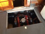
(Keep in mind this is a flywheel forward design. So the front is the back and the back is the front) (I know damned confusing!) On this engine the water comes from the pump and goes to the back of the exhaust manifolds. Then out the front and around to the back of the engine (which is the front) where the normal SBC water pump would be mounted. Then the water comes out the front corners of the intake manifold (Which would be the back corners of the engine to either side of the distributor). Then straight to the front of the risers and out.
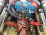
Click image for larger version  Name:	IMG_0499_s.jpg Views:	2 Size:	304.2 KB ID:	10747554

If anyone is still with me, any suggestions out there?

Cheers.......................Todd
 
Last edited:

Scott Danforth

Grumpy Vintage Moderator still playing with boats
Staff member
Joined
Jul 23, 2011
Messages
47,546
got a cooling flow diagram on the motor? the thermostat is what would regulate the temperature
 

alldodge

Moderator
Staff member
Joined
Mar 8, 2009
Messages
40,751
Hard to find info on the motors. There is a owens owner group of such

I'm in the process of restoring a 1965 Owens

If your wanting a full original original restore, then suggest getting with the folks that have them. If your just wanting to replace what you have with something more up to date, then should be able to figure out what would work like the CHV 1 83 or other.

That's a cam driven water pump, correct?
 

Sea18Horse

Chief Petty Officer
Joined
Jun 1, 2008
Messages
626
Hi Scott, This one is raw water cooled so no thermostat. It would be nice to convert it to a closed system but that would be a huge undertaking.

Hi AllDodge, I'm not worried about making it all original. What I have now, which are the CHV 1 83 manifolds is fine. And since it's a fresh water boat the manifolds and risers are in fine shape. I guess since the gaskets aren't that much money and they're not difficult to change I'll just try both styles and see if it makes a difference.

Yes it is a cam driven water pump. I changed the impellers in it a month ago or so.
Thanks guys!

Cheers...………………...Todd
 

alldodge

Moderator
Staff member
Joined
Mar 8, 2009
Messages
40,751
Even raw water cooled motors run better if there is a thermostat.

Could you post a couple more pics of the motor, one further back from the side, and one from the flywheel side?
 

Sea18Horse

Chief Petty Officer
Joined
Jun 1, 2008
Messages
626
Thanks AllDodge!
Here is a shot a little further forward. It shows the hoses coming out of the exhaust manifolds and the hoses coming out of the front of the intake and going to the risers. And the original Owens Flagships block off plate where the thermostat would ordinarily be. The manifolds are off now so I don't know how much help a picture now would be.
IMG_0411_s.jpg
I'd love to incorporate a thermostat but all of the raw water cooling setups I see have two pumps. A raw water pump and a circulating pump. The thermostat setups I find all seem to have an outlet that goes to the circulating pump. I only have a raw water pump. Granted it's dual pocket, so it does have two outlets. Trying to figure out how to set this up makes my head hurt! :) If you have any ideas I'd love to hear them! Thanks!

Cheers..............Todd
 

alldodge

Moderator
Staff member
Joined
Mar 8, 2009
Messages
40,751
So the prop shaft is being driven by the front of the crank and not the flywheel?

Is this a standard LH motor or RH?
 

Sea18Horse

Chief Petty Officer
Joined
Jun 1, 2008
Messages
626
So the prop shaft is being driven by the front of the crank and not the flywheel?

Correct. The alternator is driven by a pulley mounted to the flywheel. There's not a lot of room up there to mount a circulating pump but it could theoretically be done.

Is this a standard LH motor or RH?

Yes it's a standard LH motor. Thank god! But it does drive a right handed prop. :crazy:

Another constraint that I didn't think to mention is that the water pump is driven off the camshaft by an almost 55 year old pair of unobtainium nylon gears. So I can't afford to increase the working pressure in the cooling system at all. Which of course means that I need to find out what that pressure is before I go making changes. I really appreciate the discussion. It gives me the opportunity to think things through in a way I might not otherwise. Thank you!

Cheers.........Todd
 

alldodge

Moderator
Staff member
Joined
Mar 8, 2009
Messages
40,751
Sorry have more questions, just getting my thoughts in order, in an attempt (slim maybe) to try a figure something else

What transmission do you have?
How much room between engine to trans to prop shaft exit (assuming shaft and not outdrive)

Assuming a single engine

Guess I'm trying to figure out why they put the motor in backwards, when all they would need to do is what everyone else was doing, install a RH motor
 

Sea18Horse

Chief Petty Officer
Joined
Jun 1, 2008
Messages
626
The transmission is a Velvet Drive. A 71C I think (the tag is missing). The "bell housing" is maybe 6". And then the transmission mounting flange to prop shaft flange is maybe 12" or 14". Yes, single engine straight inboard.

As to why they put the motor in backwards, I wish I knew. I suspect it was a lot like why does Subaru do some things the way they do today? Because they can. And to kind of set themselves apart from the crowd. But probably it comes down to a more efficient use of space. Thanks.

Cheers..................Todd
 

alldodge

Moderator
Staff member
Joined
Mar 8, 2009
Messages
40,751
The 71C pump can be rotated so it can be used on LH or RH motors. I'm thinking (will cause some rework) change to direct mount the transmission to the motor. Would need to change the motor/trans mounts, but could be installed as one unit. This would be a larger undertaking, but the end result I think would be something that would work better.

Would need a lot of measurements to determine what needs to be changed and the impacts. My guess is you might not want to do this, but I'm thinking it could be done, and could to a newer version (vortec) SBC

velvet.jpg
 

Scott Danforth

Grumpy Vintage Moderator still playing with boats
Staff member
Joined
Jul 23, 2011
Messages
47,546
AD, it was common in the 50's thru the early 70's to drive off the front crank. Then someone came up with a simple casting and mounted the gear to the flywheel housing vs remote mounting it. agree, if the motor or trans dies, this would be my recommended choice.

SeaHorse, a thermostat is used to regulate the motor regardless of fresh water cooled or raw water cooled. however the motor needs to be set up properly to use that.

if you could get a pic of the whole motor, basically from the front of it like your first pic, however standing back another 6 feet or so. need to see how the whole motor is plumbed
 

alldodge

Moderator
Staff member
Joined
Mar 8, 2009
Messages
40,751
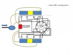
This is how I see it currently

Water comes from pump and splits in 2 places. One goes to starboard manifold, the other goes to intake where the thermostat housing would be. Water fills the block via the intake T-housing and also water passes out the other side to the port manifold.

Water exits the block thru the front block ports where the circulating water pump would be. The water exiting the block transfers thru the hoses to the riser connects where it exits the exhaust.

Water entering the exhaust manifolds also exits from mans to risers and out exhaust.

Owens cooling.jpg
 

Sea18Horse

Chief Petty Officer
Joined
Jun 1, 2008
Messages
626
Thank you so much for taking the time to draw this out. I like it. But here you say
Water comes from pump and splits in 2 places. One goes to starboard manifold,
That's the port manifold. Hehe! Confusing aint it! Anyway I like it. I'm just wondering about a couple things. I'm concerned that you have the water going in one upper fitting and out both lower fittings and the other upper fitting. It seems like it would be easy to get air trapped in the block and get localized hot spots. Especially since the front of the engine is so much higher than the back. (This might not be too clear from the photos. Sorry). I suspect that this is the reason why they have the outlet fittings in the front (back) near the distributor.

In any case I'll have to back burner this exercise for a bit.
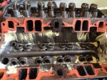
IMG_0523 (2)_s.jpgIMG_0524_s.jpgIMG_0525 (2)_s.jpg
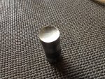
IMG_0526_s.jpg
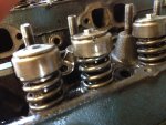
It's gonna need a valve grind, cam and lifters, cam and crank bearings and a re-ring at the least.
Thanks a lot for the suggestions. And I'll revisit this conundrum when it goes back together. I'll need to. It seems it doesn't like running this cold.

Cheers....................Todd
 
Top