On the advice of Don, I purchased the Delco EST Voyager distributor kit from http://www.michiganmotorz.com/delco-voyager-marine-electronic-distributor-p-121.html
The removal and installation of the distributor was easy. The old one was in and it was set at TDC on #1. A bit of confusion ensued when putting in the new one because of where #1 on the cap will be. #1 was at about 6 o-clock on the old. It is at about 12 0-clock on the new. The confusion was because I did not know what the direction of the wiring plugs on the new distributor were supposed to go. I initially thought they would point to the side. Of course I should have just checked the bottom of the distributor shaft because there is a slot in it so it can only go two directions. I put mine in so the wiring plugs would face the front instead of the back. I just figured this would be easier to work with.
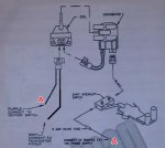
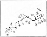
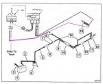
In order to make this work you have to cut wires and disconnect wires and splice wires. This caused me some trepidation for obvious reasons. I took my time and made sure I was cutting the right ones. The OMC manual helped with this because there is a resistor wire running from the alternator to the coil. The manual tells you the color of the wire. I had to peal back some of the tape to see the "real" color because of fading. This resistor wire must be removed/disconnected. The new EST needs 12 volts. The resistor wire knocked the voltage down on mine to the low 11's. The instructions are very specific about this and there are cautions all over the instruction manual about it.
If you are going to do this conversion I suggest you read the manual thoroughly and repeatedly. You will need butt end connectors, a 2amp inline fuse and holder, ring connector, dielectric grease, shrink wrap, wire ties, and electrical tape, along with a compliment of tools.
I am still in the process of connecting all the wires. I have been thwarted by rain for the last two days, and tomorrow is supposed to be worse.
I do have a question.
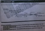
You have to have a power source for the blue wire from the shift interupt that will come on with the ignition in the "on" position. Can I run this from the purple wire from the positive side of the coil? The interupt cuts the ground part of the circuit to "stall" the motor briefly, right? Is there another power source keyed to the ignition that would be better to tap into?
The removal and installation of the distributor was easy. The old one was in and it was set at TDC on #1. A bit of confusion ensued when putting in the new one because of where #1 on the cap will be. #1 was at about 6 o-clock on the old. It is at about 12 0-clock on the new. The confusion was because I did not know what the direction of the wiring plugs on the new distributor were supposed to go. I initially thought they would point to the side. Of course I should have just checked the bottom of the distributor shaft because there is a slot in it so it can only go two directions. I put mine in so the wiring plugs would face the front instead of the back. I just figured this would be easier to work with.
In order to make this work you have to cut wires and disconnect wires and splice wires. This caused me some trepidation for obvious reasons. I took my time and made sure I was cutting the right ones. The OMC manual helped with this because there is a resistor wire running from the alternator to the coil. The manual tells you the color of the wire. I had to peal back some of the tape to see the "real" color because of fading. This resistor wire must be removed/disconnected. The new EST needs 12 volts. The resistor wire knocked the voltage down on mine to the low 11's. The instructions are very specific about this and there are cautions all over the instruction manual about it.
If you are going to do this conversion I suggest you read the manual thoroughly and repeatedly. You will need butt end connectors, a 2amp inline fuse and holder, ring connector, dielectric grease, shrink wrap, wire ties, and electrical tape, along with a compliment of tools.
I am still in the process of connecting all the wires. I have been thwarted by rain for the last two days, and tomorrow is supposed to be worse.
I do have a question.
You have to have a power source for the blue wire from the shift interupt that will come on with the ignition in the "on" position. Can I run this from the purple wire from the positive side of the coil? The interupt cuts the ground part of the circuit to "stall" the motor briefly, right? Is there another power source keyed to the ignition that would be better to tap into?