Cabin heater core blowing cold air.

Gonefishing85

Petty Officer 3rd Class
Joined
Jun 25, 2016
Messages
90
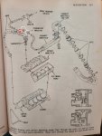
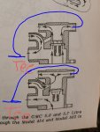
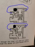
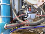
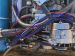
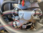
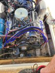
Heater blowing cold air regardless of engine temp. This is how it was plumbed when I got it. It is a closed cooling system with heat exchanger. See diagram for details. The two outlets circled in white go to the heater core. The red one is plugged off and the uncircled one goes to the heat exchanger. Looking at the thermostat flow diagram on the bottom right, it seems I should maybe have one of the hoses going to the core plugged in to the red circle in order to get circulation. Any advice? I already verified I don't have a shutoff closed somewhere.
 

Attachments

  • photo337599.jpg
    photo337599.jpg
    1.1 MB · Views: 0

alldodge

Moderator
Staff member
Joined
Mar 8, 2009
Messages
40,712
The red one is plugged off

Your motor will over heat if the red one is plugged. This is the flow of fresh water from the drive

The ones in white would go the the exhaust manifolds

If your trying to install a HE on the motor, lets start with, what motor, what year and serial numbers are best

Heater.jpg
 

Scott Danforth

Grumpy Vintage Moderator still playing with boats
Staff member
Joined
Jul 23, 2011
Messages
47,490
your heater core should be plumbed into the thermostat housing and the water pump on the suction side (big hose side). agreed, if you plug the one circled in red, you will overheat your motor
 

Bondo

Moderator
Staff member
Joined
Apr 17, 2002
Messages
70,506
This is how it was plumbed when I got it. It is a closed cooling system with heat exchanger. See diagram for details.

Ayuh,..... The cabin heater should get the hot water from the bottom of the t-stat housin', or a port in the intake manifold,......
It should return the water to a port on the circulatin' water pump housin',.....
 

Gonefishing85

Petty Officer 3rd Class
Joined
Jun 25, 2016
Messages
90
Your motor will over heat if the red one is plugged. This is the flow of fresh water from the drive

The ones in white would go the the exhaust manifolds

If your trying to install a HE on the motor, lets start with, what motor, what year and serial numbers are best


It is a closed cooling system! The fresh water comes in from the lower unit, passes through the oil cooler, enters the heat exchanger and then exits the heat exchanger exiting through the exhaust. Being as the sea water never enters the engine, the red is appropriately removed from that system. On the engine side, the coolant circulates via a water pump like any automotive system except it passes through the heat exchanger to be cooled instead of relying on air through a radiator. The engine is an early to mid 90's omc 5.7. As far as the issue with the heater, it seems as if it simply isn't circulating coolant.
 

alldodge

Moderator
Staff member
Joined
Mar 8, 2009
Messages
40,712
OK, I understand better, the issue is showing open cooling system and talking closed and heaters

For coolant to circulate thru a heater it needs to go from a higher pressure area to a lower pressure area. The low side needs to be on the circulating water pump (left side facing motor) or Tee'd into the large hose on that side.

The high side needs to come from the thermostat housing or the block.

Disconnect one of the white circle hoses connected on the thermostat and move it to the water pump. Many water pumps have a plug on the left side next to the large circulating pump.

Water heater.jpgSBC cooling-system.jpg
 

Scott Danforth

Grumpy Vintage Moderator still playing with boats
Staff member
Joined
Jul 23, 2011
Messages
47,490
It is a closed cooling system! The fresh water comes in from the lower unit, passes through the oil cooler, enters the heat exchanger and then exits the heat exchanger exiting through the exhaust. Being as the sea water never enters the engine, the red is appropriately removed from that system. On the engine side, the coolant circulates via a water pump like any automotive system except it passes through the heat exchanger to be cooled instead of relying on air through a radiator. The engine is an early to mid 90's omc 5.7. As far as the issue with the heater, it seems as if it simply isn't circulating coolant.

you posted a raw water cooled diagram, hence the confusion.

with a HX, the whole motor gets re-plumbed.

however the heater still gets plumbed to somewhere on top the intake manifold or t-stat for the hot side and the water pump for the cold side.

if that is how its plumbed, then you either have a blocked heater core or you have a valve in the system that is shut.
 

Gonefishing85

Petty Officer 3rd Class
Joined
Jun 25, 2016
Messages
90
OK, I understand better, the issue is showing open cooling system and talking closed and heaters

For coolant to circulate thru a heater it needs to go from a higher pressure area to a lower pressure area. The low side needs to be on the circulating water pump (left side facing motor) or Tee'd into the large hose on that side.

The high side needs to come from the thermostat housing or the block.

Disconnect one of the white circle hoses connected on the thermostat and move it to the water pump. Many water pumps have a plug on the left side next to the large circulating pump.


Sorry for the confusion. I posted the diagram that was in the shop manual without even considering it my cause confusion. So my next question is, should and can the thermostat housing be replaced with an automotive housing with a single outlet rather than having the original with 3 capped outlets? Or would either of these options work for the heater?
 

Attachments

  • photo337645.jpg
    photo337645.jpg
    17.9 KB · Views: 0
  • photo337646.jpg
    photo337646.jpg
    19.3 KB · Views: 0
  • photo337647.jpg
    photo337647.jpg
    191.6 KB · Views: 0
  • photo337648.jpg
    photo337648.jpg
    182.5 KB · Views: 0

Horigan

Chief Petty Officer
Joined
Jun 12, 2016
Messages
619
Rather than trying to redesign the system, I suggest figuring out why you aren't getting flow to the cabin heat exchanger, as Scott suggests. I have a similar system that has more of an automotive thermostat housing, then a four way fitting that sends hot water to the cabin heat exchanger. Yours sounds like it's different, but it will have dedicated hoses going to the cabin heat exchanger, with the supply coming from somewhere near the thermostat housing. That circuit is likely plugged. Figure out where the supply and return lines are and try to flow water directly through the cabin heat exchange with a garden hose and the appropriate fittings.
 

Gonefishing85

Petty Officer 3rd Class
Joined
Jun 25, 2016
Messages
90
Rather than trying to redesign the system, I suggest figuring out why you aren't getting flow to the cabin heat exchanger, as Scott suggests. I have a similar system that has more of an automotive thermostat housing, then a four way fitting that sends hot water to the cabin heat exchanger. Yours sounds like it's different, but it will have dedicated hoses going to the cabin heat exchanger, with the supply coming from somewhere near the thermostat housing. That circuit is likely plugged. Figure out where the supply and return lines are and try to flow water directly through the cabin heat exchange with a garden hose and the appropriate fittings.

Thank you but way past that.
 

alldodge

Moderator
Staff member
Joined
Mar 8, 2009
Messages
40,712
1st you need a place to install your temp sensor and its designed to be in the thermostat housing. If the temp sensor is not installed in the thermostat housing then it needs to be installed in the water jacket of the intake manifold next to the thermostat

2nd Heat rises and would be a place for water out and would enter the heater. If water does not come out of it, then it needs to come out of the intake or down low at the block drain. The block drain does work, it is how Formula installed on my cruiser for the hot water heater.

3rd you cannot have water out of the thermostat housing and also go back in, you will have the same issue you have now with no flow
 

Scott Danforth

Grumpy Vintage Moderator still playing with boats
Staff member
Joined
Jul 23, 2011
Messages
47,490
Sorry for the confusion. I posted the diagram that was in the shop manual without even considering it my cause confusion. So my next question is, should and can the thermostat housing be replaced with an automotive housing with a single outlet rather than having the original with 3 capped outlets? Or would either of these options work for the heater?

so are you adding a heat exchanger to a boat that didnt have one? if so, then the thermostat housing needs to change. I would also caution adding a Heat Exchanger to a boat motor that isnt new

however if you bought it that way it sounds like someone half-fasted the HX installation because the thermostat housing should have changed

lets start with a picture of what you really have in the bilge along with a sketch.

plumbing is different on a raw water cooled installation than it is on a half-system than it is on a full system. it also varies from manufacturer to manufacturer.
 

Gonefishing85

Petty Officer 3rd Class
Joined
Jun 25, 2016
Messages
90
so are you adding a heat exchanger to a boat that didnt have one? if so, then the thermostat housing needs to change. I would also caution adding a Heat Exchanger to a boat motor that isnt new

however if you bought it that way it sounds like someone half-fasted the HX installation because the thermostat housing should have changed

lets start with a picture of what you really have in the bilge along with a sketch.

plumbing is different on a raw water cooled installation than it is on a half-system than it is on a full system. it also varies from manufacturer to manufacturer.

Here it is. Blue is the fresh water system, red is the enclosed system. On t stat housing, red circle is to the exchanger, white is to the heater, black is capped off.
 

Attachments

  • photo337649.jpg
    photo337649.jpg
    1.3 MB · Views: 0
  • photo337650.jpg
    photo337650.jpg
    345.8 KB · Views: 0
  • photo337651.jpg
    photo337651.jpg
    1.2 MB · Views: 0
  • photo337652.jpg
    photo337652.jpg
    1.4 MB · Views: 0

Scott Danforth

Grumpy Vintage Moderator still playing with boats
Staff member
Joined
Jul 23, 2011
Messages
47,490
if the blue paint on the HX is original, then the blue HX cam off of an older motor and was cobbled together for your newer motor. (the blue paint was used 19 and older, the silver paint was 1980 and newer)

or it was an aftermarket setup that didnt follow the instructions.

the thermostat housing you have is a mixing style for a raw water cooled motor

got a picture of the HX and all the connections?

based on the size of the HX, it is at most a half system. is there one or two discharge hoses running to your manifolds? for aV8, there should be two, one for each manifold.

Here are pictures from an old thread with an aftermarket installation on an OMC.

fetch

fetch
 

Gonefishing85

Petty Officer 3rd Class
Joined
Jun 25, 2016
Messages
90
if the blue paint on the HX is original, then the blue HX cam off of an older motor and was cobbled together for your newer motor. (the blue paint was used 19 and older, the silver paint was 1980 and newer)

or it was an aftermarket setup that didnt follow the instructions.

the thermostat housing you have is a mixing style for a raw water cooled motor

got a picture of the HX and all the connections?

based on the size of the HX, it is at most a half system. is there one or two discharge hoses running to your manifolds? for aV8, there should be two, one for each manifold.

Here are pictures from an old thread with an aftermarket installation on an OMC.

fetch

fetch

The HX is a san jaun/orca. Here is a picture of an identical unit. It has 4 connections fresh in/out are the small ones and collant in/out are the big ones.
 

Attachments

  • photo337664.jpg
    photo337664.jpg
    17.8 KB · Views: 0

Gonefishing85

Petty Officer 3rd Class
Joined
Jun 25, 2016
Messages
90
if the blue paint on the HX is original, then the blue HX cam off of an older motor and was cobbled together for your newer motor. (the blue paint was used 19 and older, the silver paint was 1980 and newer)

or it was an aftermarket setup that didnt follow the instructions.

the thermostat housing you have is a mixing style for a raw water cooled motor

got a picture of the HX and all the connections?

based on the size of the HX, it is at most a half system. is there one or two discharge hoses running to your manifolds? for aV8, there should be two, one for each manifold.

Here are pictures from an old thread with an aftermarket installation on an OMC.

fetch

fetch

So my hx is plumbed as follows. Fresh water comes in from outdrive, passes through oil cooler then enter hx. Exits hx to a T that feeds each side ex manifold. Collant side leaves tstat housing to hx then exits hx to engine water pump then repeats cycle. So it is identical to the photos you posted to that point.

The difference is my tstat housing is clearly the original with an inlet a circulation outlet and the ex manifold feeds. What would be the fresh water inlet is plugged. The exhaust manifold feeds on the tstat housing are what feeds the heater core. My assumption is the way it is plumbed, creates equal pressure from both sides and essentially prevents flow.
 

Scott Danforth

Grumpy Vintage Moderator still playing with boats
Staff member
Joined
Jul 23, 2011
Messages
47,490
yes. you need to get a proper t-stat housing. then plumb your heater core into the intake manifold (opposite side of the temp sensor) and the return on your water pump fitting that AD pointed you to.
 

Gonefishing85

Petty Officer 3rd Class
Joined
Jun 25, 2016
Messages
90
yes. you need to get a proper t-stat housing. then plumb your heater core into the intake manifold (opposite side of the temp sensor) and the return on your water pump fitting that AD pointed you to.

I assume the proper tstat housing is a single outlet like a car?
 

Attachments

  • nal-10108470_w.jpg
    nal-10108470_w.jpg
    17.9 KB · Views: 0
Top