OMC 4.3 Closed cooling install

zigen

Cadet
Joined
Jan 17, 2019
Messages
7
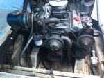
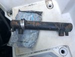
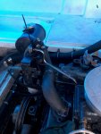
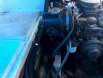
Hi, I have a new to me boat, the previous owner removed the faulty mercruiser 4.3 and bolted in a used OMC 4.3 and that is as far as they got when I purchased it. The OMC has a San Juan closed cooling system that has a seperate header tank mounted beside the fuel pump, the main heat exchanger didn't come with any brackets so I have no idea where it should go and in what orientation (i.e vertical or horizontal), if anyone has some advise so I can get some brackets made accordingly it would be greatly appreciated, some images are attached.

Thanks in advance.
 

Attachments

  • photo307072.jpg
    photo307072.jpg
    355.1 KB · Views: 1
  • photo307073.jpg
    photo307073.jpg
    267.5 KB · Views: 1
  • photo307074.jpg
    photo307074.jpg
    219.7 KB · Views: 0
  • photo307075.jpg
    photo307075.jpg
    192.6 KB · Views: 1

Scott Danforth

Grumpy Vintage Moderator still playing with boats
Staff member
Joined
Jul 23, 2011
Messages
47,486
call san juan and find out what you are missing
 

Lou C

Supreme Mariner
Joined
Nov 10, 2002
Messages
11,830
I actually called them a year or so ago thinking about eventually putting one of their systems on my next engine...and it seems that they may have gotten bought out by Orca...might want to check....

That engine looks like a later model but still pre vortec OMC with the electric fuel pump and Holley carb. The manifolds are the Merc style not the OMC/Volvo style from what I can see.
 

zigen

Cadet
Joined
Jan 17, 2019
Messages
7
Thanks Lou, the only thing I've come up with today is perhaps it is supposed to be remotely mounted, hence why the header tank is separate to the heat exchanger and no engine mounts for the exchanger were present. If anyone can confirm or correct this theory it would be appreciated. Cheers.
 

Scott Danforth

Grumpy Vintage Moderator still playing with boats
Staff member
Joined
Jul 23, 2011
Messages
47,486
the header tank is separate because its sized properly for draw down and expansion.

you need to find out if it is correct for the motor, is it sized for only a half-system, or is is sized appropriately for a full system, what brackets you need, and most importantly, how it should be plumbed.
 

zigen

Cadet
Joined
Jan 17, 2019
Messages
7
Thanks Scott.

It's a half system.

I have made a plate up to mount it on in front of the engine and started to run the lines.

I'm down to just one issue now, in the attached image the raw water input from the leg is on the far right and the output is on the far left that needs to go into the undersides of two exhaust manifolds so the raw water can cool and exit out of the risers and into the exhaust.

On the far left there are two connections though, both are different, one is barbed and designed for a hose and clamp, the other is got a bsp taper thread in it.

As I need to run two lines (one to each manifold) if I fit a hose tail into the threaded hole i could then run the two lines directly off the exchanger however the inner diameter of the added hose tail would be much smaller than the fixed/existing hose connector. So is this threaded output supposed to be instead blocked off and only the existing barbed connection used to route raw water out? (You would then need a "Y' connector to allow a line to go to each manifold). My only concern with doing this is that the size of the raw water output is significantly smaller than the diameter of raw water input, is that normal for the raw water going through a heat exchanger?

Any advice would be appreciated.
 

Attachments

  • photo307073.jpg
    photo307073.jpg
    267.5 KB · Views: 0

Horigan

Chief Petty Officer
Joined
Jun 12, 2016
Messages
619
The threaded hole is for a pencil zinc (Google it). It is a brass plug with a replacable screw-in zinc. For the raw water outlet you need a short section of hose, then a T-fitting to branch the outlet to both exhaust manifolds.
 

Scott Danforth

Grumpy Vintage Moderator still playing with boats
Staff member
Joined
Jul 23, 2011
Messages
47,486
you should not need a tee fitting. if there are not enough connections on the heat exchanger, it is not the correct heat exchanger for the application. it could be for a 3.0
 

Horigan

Chief Petty Officer
Joined
Jun 12, 2016
Messages
619
I suggest checking with San Juan/Ocra for applicability. My 5.0 V8 boat was delivered with a heat exchanger with only single raw water input/outputs. They'll need to know the length, diameter, and the diameter of the raw water fittings.

I would also suggest taking off the end caps and running a rod through the tubes to clean them out. If it were me, I'd also run a 50% solution of hydrochloric acid for 10 minutes with a spare bilge pump, clear hoses, and a small bucket. This will bring it back to like new performance. Ensure the zinc cap is place. Google heat exchange cleaning for more details.
 

aimlow

Petty Officer 2nd Class
Joined
Nov 7, 2018
Messages
180
The heat exchanger can be mounted anywhere. The cap MUST be at the high point in the engine, so that there is no "air lock". ALL hoses should slope upwards so air bleeds out.
 
Top