Mercruiser 3.0l Ignition conversion questions (with pictures)

eavega

Lieutenant
Joined
Apr 29, 2008
Messages
1,377
Okay, so I have read through the various posts of converting the points ignition to electronic ignition. I got the Ignitor II module and the matching Flamethrower II coil. I have installed the ignition module, but I am stuck on the coil and what to disconnect off the old coil and connect to the new. This is for a 1988 Mercruiser 3.0 l engine.

Here is a picture of the coil that is in there right now. It has a purple/yellow wire and a purple wire which are joined together into one connector and hooked up to the + side of the existing coil, then a grey wire (assume that is the tach signal) and the black wire from the points/condenser on the - side.
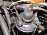
BoatWiring 005.jpg

So, my confusion is which wire do I need to remove from the coil, and which do I leave? The wiring diagram I have in the service manual (#10) says the purple/yellow wire is the "Ballast bypass", and it runs from the coil + to the starter? here is a picture of where the purple/yellow wire goes into the starter.
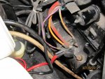
BoatWiring 004.jpg

The purple wire shown in the wiring diagram going from the coil + is labeled "purple resistance wire" and shows running from the coil to where it splices into the purple choke wire (too many friggin purple wires here). One problem I have is that I can't find where that splice is. Now, everything I have read on other threads dealing with ignition conversion says to splice in a wire from the purple choke wire BEFORE it joins the resistor wire. Would this be the wire I need to splice from then run to the coil +, and would it be okay to do it right here where it runs from the wire bundle to the choke?
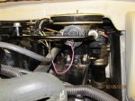
BoatWiring 006.jpg

Here's another question; can I simply separate the purple-purple/yellow wire that is connected to the coil +, tape back the purple (which I assume is the resistor wire), and leave the purple/yellow wire for my 12V? That purple/yellow wire runs to the starter, and connects up to a small post right next to the big honkin red wire from the battery. Not sure if that provides 12V when the engine is running, though.

Anyway, I am looking for any instructions as to how to proceed, which wire to tap into, and where. Other than the coil, this whole conversion thing was pretty easy. Thanks in advance for any help you all can provide.

Rgds
 
Last edited:

Don S

Honorary Moderator Emeritus
Joined
Aug 31, 2004
Messages
62,321
Re: Mercruiser 3.0l Ignition conversion questions (with pictures)

So, my confusion is which wire do I need to remove from the coil, and which do I leave? The wiring diagram I have in the service manual (#10) says the purple/yellow wire is the "Ballast bypass", and it runs from the coil + to the starter? here is a picture of where the purple/yellow wire goes into the starter.
The purple wire IS the resistor wire. It splices into the system at the choke. The terminal that plugs onto the choke has two purple wires in it (They usually do when new anyway)

The one that goes to the coil is the resistor wire, all of it.

If it does go into the bundle, then you just have to follow the resistor wire to find the splice.
 

eavega

Lieutenant
Joined
Apr 29, 2008
Messages
1,377
Re: Mercruiser 3.0l Ignition conversion questions (with pictures)

Thanks for the reply, Don S. So, from the picture in my original post, it shows only 1 wire on the connector that plugs into the choke. I traced both the purple wire from the choke and the purple wire from the coil + back to see if they were joined anywhere. They both run into a connection boot at the rear of the engine right next to the Big Red Button circuit breaker. I didn't want to disassemble the boot to see what was in there, since there were a bunch of wires running into that boot!
At this point, I just really want to know what needs to connect to the new coil, what needs to not be connected to the new coil, and if I have to splice in a wire to connect to the new coil, where do I splice it from?
Thanks again for any guidance you can provide.

Rgds
 

Bondo

Moderator
Staff member
Joined
Apr 17, 2002
Messages
70,506
Re: Mercruiser 3.0l Ignition conversion questions (with pictures)

Thanks for the reply, Don S. So, from the picture in my original post, it shows only 1 wire on the connector that plugs into the choke. I traced both the purple wire from the choke and the purple wire from the coil + back to see if they were joined anywhere. They both run into a connection boot at the rear of the engine right next to the Big Red Button circuit breaker. I didn't want to disassemble the boot to see what was in there, since there were a bunch of wires running into that boot!
At this point, I just really want to know what needs to connect to the new coil, what needs to not be connected to the new coil, and if I have to splice in a wire to connect to the new coil, where do I splice it from?
Thanks again for any guidance you can provide.

Rgds

Ayuh,... The resistance wire will have Less than 12 volts,...

Use a meter to see where you can get Key-switched 12 volts, 'n run that to the (+) on the coil, along with the striped wire from the solenoid...
 

eavega

Lieutenant
Joined
Apr 29, 2008
Messages
1,377
Re: Mercruiser 3.0l Ignition conversion questions (with pictures)

So, what I need to do is

1. Find a wire that is 12V hot only when the key is in the switch and in the "on" position.
2. Splice into that wire (what color, just to maintain standard?).
3. Undo the Purple-purple/yellow wire connector that went to the coil + to separate these two.
4. Snip and seal the purple wire, then tape it back into the mass-o-wires.
5. Terminate both the purple/yellow wire and the <Don't know what color to use> wire I spliced from the 12V-when-on source.
6. Connect to Coil + along with the red wire from the Ignitor II module.
7. Connect the black wire from the Ignitor II module and gray (tach signal?) wire to the Coil -.
8. re-tape up the mass-o-wires so it all looks neat and clean.
9. Call it done.

Did I miss anything?

Any suggestions on what wire I'm going to find is 12V hot when key switch is in ON position?
 

Bondo

Moderator
Staff member
Joined
Apr 17, 2002
Messages
70,506
Re: Mercruiser 3.0l Ignition conversion questions (with pictures)

So, what I need to do is

1. Find a wire that is 12V hot only when the key is in the switch and in the "on" position.
2. Splice into that wire (what color, just to maintain standard?).
3. Undo the Purple-purple/yellow wire connector that went to the coil + to separate these two.
4. Snip and seal the purple wire, then tape it back into the mass-o-wires.
5. Terminate both the purple/yellow wire and the <Don't know what color to use> wire I spliced from the 12V-when-on source.
6. Connect to Coil + along with the red wire from the Ignitor II module.
7. Connect the black wire from the Ignitor II module and gray (tach signal?) wire to the Coil -.
8. re-tape up the mass-o-wires so it all looks neat and clean.
9. Call it done.

Did I miss anything?

Any suggestions on what wire I'm going to find is 12V hot when key switch is in ON position?

Ayuh,... Purple is the standard for the Ignition circuit....
 

eavega

Lieutenant
Joined
Apr 29, 2008
Messages
1,377
Re: Mercruiser 3.0l Ignition conversion questions (with pictures)

Just to put this thread to rest, I located a purple wire coming off the alternator and traced it back until it got to the vicinity of the coil. I spliced into that wire and that is my 12V supply to the coil. I haven't tested it yet to check that it starts and that the timing is on, but the wiring question is resolved. Thanks to Bond-o and Don S for their help.

Rgds
 

eavega

Lieutenant
Joined
Apr 29, 2008
Messages
1,377
Re: Mercruiser 3.0l Ignition conversion questions (with pictures)

Okay, re-awakening this thread. I took the boat out of the garage today just to verify that the motor would start and to set the timing in preparation to get out on the water soon. I couldn't get the motor to start and had a question about the pertronix ignition conversion. The instructions were not clear if there was any particular position the module needed to install. I installed it with the concave side facing towards the engine. I can see it could also install the other way around (concave part part facing away from the engine). Does this make a difference? The most obvious reason the motor wouldn't start is the ignition, but I checked and I am getting spark to all four cylinders. The only thing I can think of is that its out of phase, and thus won't run. Any thoughts or suggestions would be welcome, as I am going to continue to work on this tomorrow.

Rgds
 

dubs283

Vice Admiral
Joined
Jul 27, 2005
Messages
5,092
Re: Mercruiser 3.0l Ignition conversion questions (with pictures)

the plate the module is mounted to the screws onto the distributor base should have a tab that allows you to put the cap on in one direction

there also should be a notch in the plate that allows the wires to pass through and to the coil - this is how the plate should be oriented

make sure the plate is mounted correctly, the firing order is correct and the timing is close - you may have to rotate the distributor slightly if the timing is way off
 

eavega

Lieutenant
Joined
Apr 29, 2008
Messages
1,377
Re: Mercruiser 3.0l Ignition conversion questions (with pictures)

Okay, to put this thread to bed one more time, it turns out I had two problems; the ring that goes over the distributor shaft was not seated properly, so the distributor rotor was not sitting properly on the key, and thus not rotating. A couple of gentle taps using a long socket to get it to seat properly fixed that problem. Also turns out that I had crossed up the 3 and 4 wire. It doesn't help to label the wires at the plug if you cross them up at the cap! All is well now. I tried to get the timing squared away, but on the muffs the motor idles at 1100 even in gear, and idle timing is measured at 700 RPM. I have to get it on the water and under load in order to make sure the timing is right. For the record the motor sounded smooth as silk with the timing at 8*BTDC @1100 RPM.

Otherwise, the installation was flawless, and the system works as advertised.

Rgds
 
Top