merc120_81
Petty Officer 3rd Class
- Joined
- Jun 20, 2011
- Messages
- 92
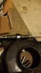
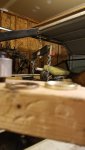
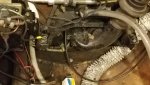
After gimble bearing replacement, just can't seem to get to align. seeing some off left/right. and have some motion on the port rear side of the motor when removing allignment tool between tweaks/tests of allignment.
I commented on another post, BT advised, to try loosening rear mounts and front lags, adjusting the engine and re-torque. I am going to give that a shot, but if that fails I want to get the parts on order ASAP.
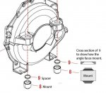
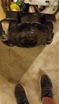
I am having an issue figuring out correct part numbers for rear mounts on the following:
1981 120 s/n 5828080 engine
Transom plate s/n 5776312
Stern Drive 5804180
I think I need bolt kit sierra
bolt kit
18-2140
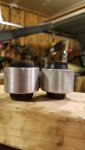
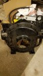
Mounts/bushings
18-2193
-I am concerned that these maybe too "new" 1983/bravo not alpha/pre-alpha mc1?
I commented on another post, BT advised, to try loosening rear mounts and front lags, adjusting the engine and re-torque. I am going to give that a shot, but if that fails I want to get the parts on order ASAP.
I am having an issue figuring out correct part numbers for rear mounts on the following:
1981 120 s/n 5828080 engine
Transom plate s/n 5776312
Stern Drive 5804180
I think I need bolt kit sierra
bolt kit
18-2140
Mounts/bushings
18-2193
-I am concerned that these maybe too "new" 1983/bravo not alpha/pre-alpha mc1?
") evening.. will report back.
evening.. will report back.