How to align a gimbal bearing, and why it needs to be done. (Inc video)

achris

More fish than mountain goat
Joined
May 19, 2004
Messages
27,468
I posted this video on a thread that someone had asked for it, but thought it would be a good idea to post it as a new thread....

Stickie?


Chris..........
 
Last edited:

Lou C

Supreme Mariner
Joined
Nov 10, 2002
Messages
11,830
Thanks for the vid and demonstration of proper tool and installation!
 

DouglasW

Petty Officer 1st Class
Joined
Apr 20, 2018
Messages
269
I don't understand why the gimbal bearing has to "gimbal" within itself. Once the drive shaft is installed, it isn't going to move anyway. That's the function of the u-joints. Is it just to allow for the surfaces of the gimbal housing and the engine coupler to be not perfectly parallel?
 

Rick Stephens

Admiral
Joined
Aug 13, 2013
Messages
6,118
I don't understand why the gimbal bearing has to "gimbal" within itself. Once the drive shaft is installed, it isn't going to move anyway. That's the function of the u-joints. Is it just to allow for the surfaces of the gimbal housing and the engine coupler to be not perfectly parallel?

Because transom angles are able to be at anywhere between 10 and 16 degrees and motor mounts are seldom installed perfectly straight.
 

Rick Stephens

Admiral
Joined
Aug 13, 2013
Messages
6,118
Thanks, the transom angle is what I was overlooking.

Well, it actually shouldn't matter, the angle of the transom, and you are mostly correct that once everything is aligned, the gimbal bearing is straight, barring manufacturing irregularities, damage or rot.

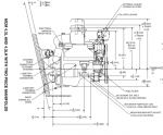
If the transom angle is steeper, the front of the motor ends up being higher. The angle of the motor to the transom plate is supposed to be exactly the same, 13º, in every installation. However, if that bearing was a fixed bearing, you could never get the alignment bar in unless the engine was perfectly aligned already. And if there were any flex, the pressure on the drive shaft would be high, and vibrations could damage transom plate.

Here's one engine drawing where you can see the angle between transom plate and engine is always 13º.

Rick

Screen Shot 2018-11-29 at 7.26.56 PM.png
 

Lou C

Supreme Mariner
Joined
Nov 10, 2002
Messages
11,830
I guess that allows a lot of freedom in boat design otherwise the transom angle and motor mounts would have to be exactly square to one another....
 

achris

More fish than mountain goat
Joined
May 19, 2004
Messages
27,468
Thanks, the transom angle is what I was overlooking.

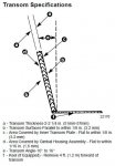
Merc's tolerance for the transom allows for variations. (See drawing below) These variations cause the alignment between the gimbal housing and the engine to also vary very slightly. If the gimbal bearing was solid and fixed, then boat builders would be required to build transoms to impossible tolerances... The bearing gimballing allows the yoke and engine coupler to be aligned without putting undue side loadings on the gimbal housing...

The transom angle restriction of 13° +/-3° is more to do with the amount of travel on the engine side mounts. If the transom angle was more than 16°, the engine would need to come up higher than the threads on the mount would allow. Less than 10° would require to have the engine down beyond the bottom of the threads... Simple geometry tells us that 6° of variation at the transom would require 53mm (2") of movement at the engine side mount on a V8 (only slightly less on a V6)... The threaded section of the mount is....2" long....

HTH,

Chris...........

transom.JPG
 

sidingguy

Petty Officer 2nd Class
Joined
Nov 3, 2017
Messages
136
Great video.This answers so many questions about why I had problems aligning my outdrive.
 
Top