Vortec Head Modification/Upgrade

Lou C

Supreme Mariner
Joined
Nov 10, 2002
Messages
11,831
True, they should have verified that those springs would work with the cam lift. And that information was available from the cam manufacturer anyway. Well now Tony you are the iboats expert on coil bind! Anyone who wants to use a high performance camshaft can ask you what to do!
 

FreeBeeTony

Captain
Joined
May 15, 2002
Messages
3,991
1st head completed: screw-in studs & new springs installed.
Looking forward to spring......and working on the 2nd head!
 

Attachments

  • photo306472.jpg
    photo306472.jpg
    47.3 KB · Views: 0
  • photo306473.jpg
    photo306473.jpg
    46.3 KB · Views: 0

whiskeyRichard

Petty Officer 3rd Class
Joined
Sep 16, 2018
Messages
96
Out of curiosity, why did you not use the beehive springs with their retainers to get the additional valve clearance?

I talked to comp cams about running this same cam with vortec heads and that is what they told me to do.

I did not read this entire thread, so sorry if this has already been discussed.

wR
 

whiskeyRichard

Petty Officer 3rd Class
Joined
Sep 16, 2018
Messages
96
I just read through the rest of the thread. So when the machine shop did the original work for you it sounds like they put on the beehive springs....is that correct?

I was told by the tech at comp cams that would create plenty of lift for the XM270HR cam.

Any idea why that did not work?

wR
 

FreeBeeTony

Captain
Joined
May 15, 2002
Messages
3,991
My machine shop did not install the Beehive springs from CompCams, he had the springs and told me they should work, not sure what springs he used and I didn't check for coil bind when I assembled the engine. I decided to go with the "old-school" springs; they were less expensive. I would definitely check the clearance of the retainer to the valve guide when installing the Beehive springs. Notice that the CompCams webpage says machining is required. Make sure the tech you speak to at CompCams knows you're installing the springs on Vortec heads. I will try to answer any questions you may have. Might also want to consider changing to screw-in rocker studs.
 

FreeBeeTony

Captain
Joined
May 15, 2002
Messages
3,991
Wanted to highlight these things I learned along my journey:


1) Another difference between Vortec valves and the earlier non self aligning head valves is the tip length. Earlier valves are 0.250" on both intake and exhaust valves. Self aligning head intake valves have a 0.260" groove-to-tip length, exhaust valves use a 0.289" groove-to-tip length. That said, the typical SBC valve tip length of 0.250" will work just fine with self aligning rockers. Like with ANY rocker arm/valvetrain combination, the
valve train geometry
needs to be verified.

2)
Warning
Note:
On Vortec and other heads using self aligning rocker arms, using a +0.050" lock can cause interference between the rocker tip and the locks/retainer. Rocker contacting the locks/retainer has been encountered using a combination of c/n 906 Vortec heads, Comp Pro Magnum rockers p/n 1317, Comp retainer p/n 787, Comp spring p/n 26918, and the +0.050" locks.

The engine builder must mock up the assembly and check the clearance closely. In the case there's insufficient clearance, there are a few options:
  • Use non self aligning rocker arms. Requires guide plates be installed.
  • Use longer valves
  • Use a different spring/retainer combo that uses a standard lock
  • If just the locks are hitting the rocker, using a shorter (lash cap compatible) lock like the Edelbrock p/n 9615 may help. This 7 degree lock is 0.050" lower than a regular lock.
  • Warning
    Use extreme caution if making the spring seat any deeper.
I contacted CompCams and their response was that they have not heard of the problem as I described.

3)
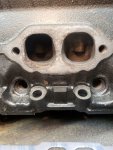
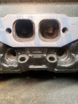
The Vortec head features a very large boss at the base of the valve guide that measures 0.850-inch in diameter and is used to locate the 1.250-inch outside diameter (O.D.) valve spring. The head uses 0.560-inch I.D. seals mounted directly on the top of the guide. This guide boss is also very tall. This height restricts the room between the top of the seal and the bottom of the valve spring retainer at max valve lift. There are two simple approaches to modifying the head to accept a performance valve spring that will create the room necessary to allow greater valve lift.

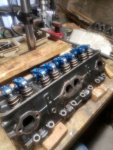
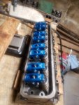
4)
The second solution is less expensive but requires more effort and to purchase a machine tool to modify the valve guide boss to add clearance. COMP sells a slick little tool that will machine the guide down to a 0.530-inch O.D. seal size while also lowering the boss height. The boss height of our heads measured 0.730-inch from the spring seat. It is this height that minimizes the seal-to-retainer clearance. With the tool set up in our ½-inch drill motor, it took a few minutes to machine all 16 guide bosses, being careful to lower the guide height only enough to create 0.550-inch retainer-to-seal clearance.

I found these (4) bits of info on the internet and cut/pasted them here. Hope this helps.........
 

whiskeyRichard

Petty Officer 3rd Class
Joined
Sep 16, 2018
Messages
96
ugh, thanks for the info.

I guess I need to take everything those techs from Comp Cams say with a grain of salt.....and make sure to read the fine print.


wR
 

scoflaw

Ensign
Joined
Jun 2, 2010
Messages
962
I would go with longer valve stems before I make my guides shorter. The guide is going to be subjected to more wear with a larger cam and making it shorter isn't going to help matters.
 

FreeBeeTony

Captain
Joined
May 15, 2002
Messages
3,991
I would go with longer valve stems before I make my guides shorter. The guide is going to be subjected to more wear with a larger cam and making it shorter isn't going to help matters.

That would require a "valve-job".........correct?
New seats etc.....?
 

scoflaw

Ensign
Joined
Jun 2, 2010
Messages
962
The valve face is the same, the stem is longer. So if your seats are good now the longer stem isn't going to change anything. You will then probably need longer pushrods as well when you fine tune the rocker geometry
 

achris

More fish than mountain goat
Joined
May 19, 2004
Messages
27,468
The valve face is the same, the stem is longer. So if your seats are good now the longer stem isn't going to change anything. You will then probably need longer pushrods as well when you fine tune the rocker geometry

Longer? I would think if the valve stem is longer, that would push the rocker up higher at the valve end, which means lower at the rod end. So you'd need shorter rods..... Am I wrong somehow?

Chris...
 
Last edited:

scoflaw

Ensign
Joined
Jun 2, 2010
Messages
962
This is where the adjustable pushrod comes in to figure out what length your looking for according to the pattern on top of the valve stem.
 

FreeBeeTony

Captain
Joined
May 15, 2002
Messages
3,991
2nd Head machining complete except for tapping the rocker studs; hope to do that tomorrow.
 

Attachments

  • photo306837.jpg
    photo306837.jpg
    58.6 KB · Views: 2
  • photo306838.jpg
    photo306838.jpg
    56.9 KB · Views: 2

FreeBeeTony

Captain
Joined
May 15, 2002
Messages
3,991
Exhaust Port Matching

Starting to finalize the work I have done on my Vortec heads. Laid an exhaust gasket over the head and it seems like there's a lot of material inside the gasket opening.....see pics.

Using a grinding tool I opened the exhaust ports a bit............there's more to be had, just not sure there is any benefit to it. Don't plan on touching the intake ports.
 

Attachments

  • photo307193.jpg
    photo307193.jpg
    62.8 KB · Views: 0
  • photo307194.jpg
    photo307194.jpg
    56 KB · Views: 0
  • photo307195.jpg
    photo307195.jpg
    60.7 KB · Views: 0
  • photo307196.jpg
    photo307196.jpg
    51.6 KB · Views: 0

GA_Boater

Honorary Moderator Emeritus
Joined
May 24, 2011
Messages
49,038
You're doing it again. Please keep head mods/upgrade subjects together in this thread.

This thread certainly hasn't been ignored, it has plenty of feedback, don't ya think?

How does the gasket match up with the exhaust manifold? It takes two to tango.
 

Scott Danforth

Grumpy Vintage Moderator still playing with boats
Staff member
Joined
Jul 23, 2011
Messages
47,495
Scott Danforth Check to see if your post was lost as it was done while I was moving the porting post to this thread.

It was.....

My comment was to check the port match on both the exhaust as well as the heads

Also, spend some time blending the exhaust bowls as well as smoothing out the combustion chamber
 

FreeBeeTony

Captain
Joined
May 15, 2002
Messages
3,991
I started a separate thread in the event it wasn't worth the effort........my apologies.
I did check the gasket vs the exhaust manifold..........the openings on the manifold match those on the gasket.
So it would be beneficial to match the exhaust ports of the head to the ports of the manifold?
 
Top