Wiring In Electric Fuel Pump

Status
Not open for further replies.

Quarterwave

Petty Officer 2nd Class
Joined
Sep 16, 2013
Messages
118
Hi everyone,

I'm trying to incorporate an electric fuel pump into a 5.7 Mercruiser.

The prior engine (5.0) had a mechanical fuel pump but the replacement engine does not have all of the holes for the mechanical fuel pump built into the block.

Some notes:

1) The replacement engine is on an engine stand in a garage, so I have full access to all the components.
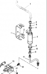
2) The electric fuel pump is a Carter model (P4389 if I recall correctly).
3) I mounted the pump in the same location as the mechanical pump (using a bracket) and have all the fuel hoses (A1 type) connected to the water/fuel separator and also to the carburetor.
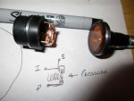
3) I have cleaned up the wiring harness from the old engine, but will need to replace most of the connectors as they are corroded.
4) I have little knowledge regarding electrics but a lot of common sense and building experience (engines and houses).

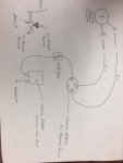
That all being said, can anyone steer me in the right direction and impart some knowledge to help me make the pump deliver fuel to the engine as required, and control the fuel system via the main ignition on/off key?

I have no extra wiring lying around etc... so anything other than the pump and hoses will need to be mentioned, so that I can buy what is needed.

Any help is very much appreciated.

Thank you.
 

Silvertip

Supreme Mariner
Joined
Sep 22, 2003
Messages
28,762
Since electric fuel pumps need a safety circuit to kill the pump should the engine die, you need an oil pressure sender that has the dual circuit (oil light and fuel pump). Since the engine would not have oil pressure, the fuel pump would not run unless that circuit was bypassed while cranking. You need a diagram from any model that has an electric fuel pump.
 

Rick Stephens

Admiral
Joined
Aug 13, 2013
Messages
6,118
I just did this process last year. And like you, I had the engine sitting on a stand, so I was able to make really clean wiring harnesses. You need two sources for turning on the fuel pump. And I would really advise you put a solenoid on the pump so you don't draw that power through an oil pressure switch.

So a fused battery wire to a solenoid to the hot side of the pump.

Then take purple wire, which is hot from ignition, and go from that to an oil pressure switch. Mine was mounted off the oil pressure sensor by teeing the 1/8th inch pipe thread at the back of the intake manifold. So purple to an oil pressure switch to the on switch side of the new solenoid. Then a second wire goes from that same location too the outside lug of the starter solenoid. This wire runs the electric fuel pump while the engine is cranking.

In the picture below Mercruisers recommended method. Power to the pump comes from either outside lug on starter or from oil switch. Those go to the solenoid instead.

wire.png
 

Quarterwave

Petty Officer 2nd Class
Joined
Sep 16, 2013
Messages
118
Thanks everyone.

Rick:

1) What gauge wire was needed and where can I get it from?
2) What types of solenoid and where can I get it from?
3) What size fuse/holder and where can I get it from?

Thanks.
 

Rick Stephens

Admiral
Joined
Aug 13, 2013
Messages
6,118
Qw,

1) I'd use 14 gauge. Mostly 'cause I always have a lot in different colors. Do pick colors that are easy to trace later.

2) I picked up a sealed relay from my local Napa. Somehting like this.

3) Any sealed fuse holder, like this.


Note, I am not recommending from Amazon. Either of those products are easier gotten from a local auto parts store.
 

Quarterwave

Petty Officer 2nd Class
Joined
Sep 16, 2013
Messages
118
Perfect, thanks Rick.

Question - would it be too much trouble to ask you to post a couple of pics of how it's set up on your engine?

Also - is automotive cable ok to use in an enclosed engine bay?
 

Bondo

Moderator
Staff member
Joined
Apr 17, 2002
Messages
70,513
Also - is automotive cable ok to use in an enclosed engine bay?

Ayuh,..... I've wired alota hulls with Belden cablin' from my local Napa,.....

Fortunately, No saltwater up here on the sweetwater seas,....

No doubt, tinned marine cablin' is Better,.....
 

Rick Stephens

Admiral
Joined
Aug 13, 2013
Messages
6,118
Perfect, thanks Rick.

Question - would it be too much trouble to ask you to post a couple of pics of how it's set up on your engine?

Also - is automotive cable ok to use in an enclosed engine bay?

I used what I get from my trailer parts supplier, which is plain ol copper wire like from Napa. My boat is 1005 fresh water and stored indoors, so I am not worried at all about it getting corroded.

Here's a photo where you can see the relay bolted into the plate with the big plug, starter solenoid and circuit breaker, lower left corner. I'll have to see if I can get you a picture of the pressure switch. I purchased the OEM Mercruiser stainless fuel line and electric pump mounting hardware so I would have a stock setup.

fuel system.jpg
 

Quarterwave

Petty Officer 2nd Class
Joined
Sep 16, 2013
Messages
118
Thanks Rick and Bondo. I picked up the parts and some marine grade wire as I'm in saltwater down here in South Florida. One more question - where are you mounting the bracket to? Is it off the fuel/water separator bracket?
 

Rick Stephens

Admiral
Joined
Aug 13, 2013
Messages
6,118
For the fuel pump I basically got all the original mercruiser mounting hardware and the plumbing from pump to carburetor. Since I purchased a new Edelbrock 1409 carb I was able to use the fuel line that fits the Weber - they are the same carburetor. The bracket shown in the picture uses one 3/8ths bolt into the end of the cylinder head and is completely separate from the stock water separator. My boat did not come from factory with a separator so I made my own bracket and mounted one between motor and tank.

Since this picture I put the primer bulb for the kicker external between transom connection and outboard - it is not legal to have a bulb in the bilge where it won't resist flame for a certain amount of time. So it got moved.

I did not get #11, the lower fuel line or any of the separator parts.


Click image for larger version  Name:	Screen Shot 2018-06-28 at 4.01.44 PM.png Views:	1 Size:	66.3 KB ID:	10600846
 

Attachments

  • Screen Shot 2018-06-28 at 4.01.44 PM.png
    Screen Shot 2018-06-28 at 4.01.44 PM.png
    66.3 KB · Views: 32

Bondo

Moderator
Staff member
Joined
Apr 17, 2002
Messages
70,513
One more question - where are you mounting the bracket to? Is it off the fuel/water separator bracket?

Ayuh,.... Mine's Oem, but that's a how ever, where ever ya can, kinda thing,.....
 

NHGuy

Captain
Joined
May 21, 2009
Messages
3,631
I did a similar thing but I went and found the Mercruiser diagram for a carbed electric pump. That way the wiring is to spec. I could not find the purple wire with yellow so I ordered some yellow marker shrink wrap and slid that onto my purple fuel pump wiring. Holley has a nice diagram in their website too if you'd like further clarification.
I'd like to recommend that you make up the metal fuel lines with copper nickel because it bends much more easily than steel, which I used and had a lot of trouble with.
If you install a fuel pressure regulator, which I recommend, it can go out in front of the engine where it is easy to access for future adjustments Since most fuel pressure regulators have bottom inlets and side outlets it can replace a 90 degree bend.
When running your fuel line be sure to isolate it from the engine and cooling lines. Heat and vibration are bad over the long term. You can stand the lines off of things with those band wraps that have rubber inside to cushion the tubing.

Like Rick, I also tee'd off the oil pressure port at the rear top of the engine to get a pressure sensor for the fuel pump. I used brass hardware store parts. Works great and is easy to reach in case of trouble.

Once you are wired and built, run the engine out of the boat. Run it to full temperature, set the timing and adjust the idle mixture. Check and solve any leaks. I have cool valve covers that leak oil with the rubber reusable gaskets.
I have my 4th set of valve cover gaskets coming this weekend. I finally gave up on the reusable silicon rubber cause they won't keep the oil in on my fancy heads and valve covers. They say the definition of insanity is doing the same thing over and over expecting different results. Guess I am boat insane!
Problems like that are way easier to deal with outside the boat.
Hope you are boating soon!
 

jones01m

Petty Officer 1st Class
Joined
May 23, 2011
Messages
252
Attached sketch is what was implemented on my project. The first pressure switch I received was bad. I would recommend testing with compressed air and voltmeter before installation. Works great.
 

Attachments

  • photo294426.jpg
    photo294426.jpg
    58.6 KB · Views: 113

Rick Stephens

Admiral
Joined
Aug 13, 2013
Messages
6,118
Attached sketch is what was implemented on my project. The first pressure switch I received was bad. I would recommend testing with compressed air and voltmeter before installation. Works great.

jones01m, the proper way is with a relay. Loading an oil pressure switch with the constant duty load of an electric fuel pump will eventually fail the oil pressure switch. I would add the relay power source and use the oil pressure switch and starter as the on off source for the relay.

Your system works great, until your start wire from the ignition switch gets back fed once the oil pressure switch comes online. Then it engages the starter solenoid from the oil pressure switch. No good. I get it that the Carter oil pressure switch probably is diode blocked off the starter circuit, so it might not back feed, but the relay is much safer arrangement for power sourcing and the outer lug on the starter solenoid is purposed for primer power during cranking.


Click image for larger version  Name:	wiring.png Views:	1 Size:	237.3 KB ID:	10601300
 

jones01m

Petty Officer 1st Class
Joined
May 23, 2011
Messages
252
Rick, you have me thinking for sure about the current going through the pressure switch. Duty cycle, etc. So, I turned a pressure switch down on a lathe to open it up and see the internals. I think, at least for the pressure switch I used, it will be robust for long term. I believe the relay you spoke to is even much more robust - I like that set-up alot.

I don't have a functioning current meter, but would have liked to have measured it through the circuit

video attached. What is your thoughts...?


jones01m

Petty Officer 1st Class
Joined
May 23, 2011
Messages
252
folks, sorry to belabor the topic.

I dug into this switch a bit more to see the internal workings by hammering the terminals back through the switch body. The switch is just a copper washer that pivots on the "P" terminal with a spring loading it towards the "S" terminal. At pressure, oil pushes on a plastic covering that loads the washer enough to overcome the spring force. At this point the washer makes contact with the "I" terminal while still engaged on the pivot at the "P" terminal.

I believe Rick's assessment is right on with the addition of the solenoid, especially with pressure switches that use more sophisticated (and likely more sensitive) circuit elements. There are photos out there that show these internals.

With that said, I also believe that this very simple switch as shown dissected in the photo is likely adequate for long term use without a solenoid. I do now have a few concerns about corrosion starting to occur on the bare copper inside and will therefore be adding some sealant around the three exposed terminals. Again, I am no expert. Just trying to understand how this all works, and will reiterate that the system Rick has shown still appears more robust overall. Hope Quarterwave the data useful.
 

Attachments

  • photo294496.jpg
    photo294496.jpg
    217.6 KB · Views: 11

Rick Stephens

Admiral
Joined
Aug 13, 2013
Messages
6,118
I like it. Great little video investigation. That is a nice little oil pressure switch. Failure point would be carbonization of the contacts. Usual failure point of a relay is the electromagnet inside them. Both are relatively easy to jumper around in the case of failure while out on the wet.

Thanks for posting!

Rick
 

Quarterwave

Petty Officer 2nd Class
Joined
Sep 16, 2013
Messages
118
Thanks for all of the information, everyone.

I was working on the wiring today, but came across more issues....

Rick - in the Mercruiser diagram from the factory service manual that you provided earlier on in this thread, you advised to cut the positive wire from the fuel pump that leads to the battery. A few questions on how I am interpreting your diagram:

1) What gauge wiring should that be? Is the 14 gauge (same as the other wiring) be ok, or do I need to use 8 gauge like the ground?

2) Also, what size fuse should I use? The link from your earlier post linked to a 30 amp fuse holder. Is that the correct amp holder (and fuse) or should it be smaller? If smaller, what size fuse?

3) There are two wires coming from the fuse holder. What colors do I use from the solenoid to wire up the fuse holder, and what wires do I use from the solenoid back into the purple/yellow wire that runs from the starter to the fuel pump, and into the oil pressure switch (which I believe is a purple wire that I need to splice into)?

4) What terminal on the fuel pump (positive/negative) do I hook that purple/yellow wire to?

5) I am confused about the oil pressure switch. I "think" I have one, but are not sure. Please see the pic attached. Is that it? If so, I have more questions about mounting the bracket that it's on, but I'll make that a new post.

6) What should I use for the splice? As my new carburetor (Edelbrock 600 cfm) has an electric choke, and the wiring diagram says to tap into that purple/yellow wire and run that to the choke.

Thanks again everyone,
 

Attachments

  • photo294628.jpg
    photo294628.jpg
    300.5 KB · Views: 26

Rick Stephens

Admiral
Joined
Aug 13, 2013
Messages
6,118
Thanks for all of the information, everyone.

I was working on the wiring today, but came across more issues....

Rick - in the Mercruiser diagram from the factory service manual that you provided earlier on in this thread, you advised to cut the positive wire from the fuel pump that leads to the battery. A few questions on how I am interpreting your diagram:

1) What gauge wiring should that be? Is the 14 gauge (same as the other wiring) be ok, or do I need to use 8 gauge like the ground?

All wiring for the fuel pump 14 gauge.

2) Also, what size fuse should I use? The link from your earlier post linked to a 30 amp fuse holder. Is that the correct amp holder (and fuse) or should it be smaller? If smaller, what size fuse?

Use a 10 amp fuse. (blue)

3) There are two wires coming from the fuse holder. What colors do I use from the solenoid to wire up the fuse holder, and what wires do I use from the solenoid back into the purple/yellow wire that runs from the starter to the fuel pump, and into the oil pressure switch (which I believe is a purple wire that I need to splice into)?

I would use red from a battery source - the circuit breaker or starter solenoid next to it both have easy access to battery power that you can tap into with a simple eye.(both of those are in your picture)

I would use yellow from pressure switch to relay and from starter outer lug to relay - both are the on off wire for the relay. From the power out on the relay use red to the pump positive then the pump negative wire goes to ground.

4) What terminal on the fuel pump (positive/negative) do I hook that purple/yellow wire to?

As in 3, hook the negative wire from the pump to a ground. The power wire off the relay goes to positive.

5) I am confused about the oil pressure switch. I "think" I have one, but are not sure. Please see the pic attached. Is that it? If so, I have more questions about mounting the bracket that it's on, but I'll make that a new post.

You need to purchase a oil pressure switch and a 1/8th pipe thread tee to plumb it in at the back of the intake to where your oil pressure sensor is. The oil pressure switch will have two lugs to attach wires, when there is oil pressure, those two lugs are electrically connected to each other. So purple - ignition power, goes to one side, yellow to operate the relay goes on the other.

6) What should I use for the splice? As my new carburetor (Edelbrock 600 cfm) has an electric choke, and the wiring diagram says to tap into that purple/yellow wire and run that to the choke.

Most of the time I use marine crimp/butt connectors. What makes them marine? - the are heat shrink and seal over the wires with a little heat applied. That and eyes on the end where you can take grounds or power from a screw terminal - like those at the pictured starter solenoid and circuit breaker.
 

Quarterwave

Petty Officer 2nd Class
Joined
Sep 16, 2013
Messages
118
Thanks Rick!

Re point #5, I actually have that, which on my engine, is located next to the distributor. I actually tested it today where is ran around 224 ohms @ 0 oil pressure (over a few seconds, it varied up to about 245 ohms). However, I recall it only having one, small threaded connector on the end. The other end bolted into the intake manifold. Am I missing something?

Re the last point (#6), I mis-worded my question. Is there a 3 or 4-way connector that I should be looking for? Or just peel back the plastic sleeve and expose the wiring, and then fray that wiring, wind the new wiring into that existing wiring, solder and heat shrink?
 
Last edited:
Status
Not open for further replies.
Top