Best way to pry off regulator/rectifier from gasket and flywheel key question.

havoc_squad

Senior Chief Petty Officer
Joined
Mar 5, 2011
Messages
702
I am on the last part of the electrical/ignition teardown of the powerhead of 1990 V4 90 HP crossflow outboard, which is trying to get the rectifier/regulator freed of the gasket on the powerhead.

Everything else has been removed involving the flywheel, charge coil, timer base, power pack, etc.

1. Is there any tips on getting this thing off without buying an adjustable spanner wrench, like what is used for the lower unit driveshaft seal cover?

2. How do you nudge the flywheel key out of the crankshaft when it is wedged in? Trying to avoid destroying the tip of a screwdriver and prevent defacing the flywheel section of the crankshaft.


I "read" that the rectifier/regulator is one of those parts you don't want to be going and prying where the gasket is, but use other methods to get it off.

I Cautiously gave some lumps to nudge it around in key spots with dead blow polymer hammer and a metal punch with leather on the tip to prevent deforming the housing, but couldn't get anything to budge.


If adjustable spanner is the only effective option, where to get it and what size/model is best to get? I seriously doubt iBoats carries that specific of a tool.

I measured something around 3 inches possible working, unless you needed to span it long-ways, which would require a 4 inch span.
 

havoc_squad

Senior Chief Petty Officer
Joined
Mar 5, 2011
Messages
702
I think I just came up with a simple solution that would be more of the hillbilly/reckneck line of thinking but work safely/correctly.

I think I'm going to find/make a 2 foot long spare 2x4, map out the hole spacing precisely, drill the holes in the board.

Then put some simple 1/4 diameter bolt hardware in with washers to clamp the wood and nuts to give the 1/2 spacing I need to clear the wiring for the bolt head.

I'll probably do all four holes in the board to give equal torquing force on the regulator/rectifier housing.

Make sure the tips are shallow enough that they don't touch the threaded portion in the block.

Insert homemade spanner wrench tips, whack board in both directions to free it up, call it done.


It's either this or wait for several days for a spanner wrench to be delivered or pray that whacking the side of it with a 2x4 board end will free it up.
 

racerone

Supreme Mariner
Joined
Dec 28, 2013
Messages
36,269
Just took one off a 95 model today.----Screw driver between the upper bearing housing and the rectifier / regulator and it popped off.----Just like on many other motors I have done !
 

havoc_squad

Senior Chief Petty Officer
Joined
Mar 5, 2011
Messages
702
Well, didn't use a screwdriver like you did racer, but the spanner wrench tip I got was a good start.

If I seen this post before I made the tool and got it off, I might have eyeballed to see where you are speaking of to get the leverage to motivate it off using a screwdriver before I used my improvised special tool.

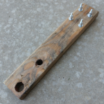
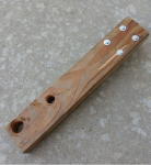
That tool I mentioned I was talking about fabricating in hillbilly fashion, it's real now.

Maybe this is somewhat overkill for trying to remove this, but I'll take small creative successes to make things easier and safer to remove. Even if no one else ends up using this idea.


Improvised Special tool info:
For removing the rectifier/regulator of part number #0583529 used on certain OMC V4 and V6 crossflows without using a pry tool.

This is for someone that does not have immediate access locally to an adjustable spanner wrench that can reach up to 4 inches span with 1/4 pin diameter. You could possibly remove it using a 2 inch exact spanner wrench with 1/4 inch pins.


Bill of materials:

1/4" x 3 " long coarse thread bolts. Qty 4

1/4" coarse thread regular nuts. Qty 12

1/4" standard flat washers. Qty 8

1/4" lock washers. Qty 4

2 to 3 foot long regular 2 x 4 lumber. Qty 1


Total cost of materials was probably around $4 to $5 US dollars to make this improvised special tool.


Hole measurements:

The hole spacing is rectangular with no odd spacing.

Horizontally, the distance is exactly 2 inches center to center for the holes, which might make it possible to just use a fixed 2 inch spanner wrench.

Vertically, the holes center to center is 2 inches 9/16".


Fabricating notes:

Make sure you try to get as close to the edge of your board to start the holes while leaving at least 1 inch of space from the top edge and 3/4 inch distance from the side edges of the board for structural reasons. The small gap at the top will reduce the likelihood of bumping the board into things, although the clearance "should" be enough with the number of nuts and washers.

It is not super critical to get the holes super perfect, you can move the drill bit around to make "small" adjustments for alignment reasons.

Took me only an hour to make it using a conventional power drill, test fit the bolts in the board with the rectifier holes, widen holes if need be, and final snug the fasteners into the board with them in the rectifier screw holes.

Eight seconds of careful whacking the edge of the board with dead blow hammer left or right and the thing was off super easy with no signs of damage to the rectifier holes. A regular hammer works fine, dead blows make it easier on me for control and less wrist strain.​


So if the mods see it as a helpful improvised tool, feel free to take the info and post it in the tips section of the forum.

I now await the influx of reviews of the attempt, whether meh, terrible, or good.
 

Attachments

  • photo319058.png
    photo319058.png
    601.9 KB · Views: 0
  • photo319059.png
    photo319059.png
    820.5 KB · Views: 0

havoc_squad

Senior Chief Petty Officer
Joined
Mar 5, 2011
Messages
702
Regarding the flywheel key, I remember that it has to be positioned right according to what the service manual says on being vertical in the flywheel key hole upon installation of the flywheel back on and I am trying to bag and tag things for removal so they are not misplaced or damaged.

Right now it's wedged into its slot very tight and it's at a 70'ish degree angle, almost matching the taper of the crankshaft surface for the flywheel.

Attached photo of flywheel key.


I'll leave it in/leave it be if that's the way the flywheel key needs to be for re-assembly.
 

Attachments

  • photo319061.jpg
    photo319061.jpg
    131.3 KB · Views: 0
Top