1969 Johnson 55hp

Hab

Petty Officer 2nd Class
Joined
Jul 4, 2017
Messages
158
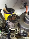
Im guessing wont be too many here interested in this but i thought id document my failures anyhow. I have (2) of these. Both have disintegrated wiring, and have not run for many years. Dad and I played with one a few years ago, trying to convert to a better or at least simpler ignition system, but got derailed when we started checking the electric shift gizmos.
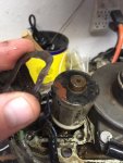
Anyway, i got one of the amplifiers the other day and started to tear it up. I cut out the soft potting, and used soldering irons, picks, ans screwdrivers to remove the harder potting. Not sure if i can remove the PCB and rebuild but I'm going to attempt it anyway. I did manage to find and remove (5) screws securing the board to the outer case. hopefully i can remove the remaining potting bonding it to the case this evening.
6-21-19.jpg6-21-19-1.jpg
 

F_R

Supreme Mariner
Joined
Jul 7, 2006
Messages
28,195
Good luck. I tried that years ago, and failed. you might do better
 

Hab

Petty Officer 2nd Class
Joined
Jul 4, 2017
Messages
158
Thanks F_R Im guessing it wont work out, but i have to try. How far did you manage to get with it? I got the PCB out, but there was a part that was embedded in the aluminum that i broke out and haven't dug out of the case yet. Ive managed to de-pot the majority of it without significant damage. now the less painful part of identifying circuits and testing components.

6-23-19.jpg6-22-19-2.jpg6-22-19-3.jpg6-22-19-4.jpg
 

Tim Frank

Vice Admiral
Joined
Jul 29, 2008
Messages
5,333
I rewired my '68 TR-10 and it ran well for another 8 years.
If you are interested you can look for some posts I made on this topic.
Others have asked about rewiring these models.
Deteriorated wiring puts a larger load on ignition components and they often fail
 

Hab

Petty Officer 2nd Class
Joined
Jul 4, 2017
Messages
158
Hey Tim, ill look for your posts as well. Im kind of confused about this whole thing. Seems like the amplifier is an early CDI type ignition with a 300V output. Im trying to figure out why a motorcycle CDI module wouldn't work in its place
 

Hab

Petty Officer 2nd Class
Joined
Jul 4, 2017
Messages
158
Hard to find clear cut answers for this one. I never did find Tim's work, i guess i was entering the wrong search terms.

Here is what I have learned so far. The amplifier is a primitive CDI system. Its output is 300V or so. the coil steps that voltage up to 30000V. The system uses a mechanical advance under the flywheel. the points are a low voltage (12V) trigger to the CDI/amplifier.

Options.
1. I have plans to build a simple CDI circuit that will be capable of charging and discharging the 300V at any required rate. however i have not built a PCB before and in trying to put a parts list together im near the $100 dollar range without fouling it up 2-3X.
2 Use an off the shelf Automotive CDI box, like the MSD. I think these will work, but they do have the capability of internally regulated electronic advance. consequences of that is unknown as of yet.
3. Rig an off the shelf GM HEI module. should work with the mechanical advance and is fairly cheap to attempt. Apparently a you tuber has managed this with the help of a stand alone transistor, but i cant figure out why the extra transistor is needed. I cannot yet find specifics on what the output voltage is, so im still hoping there.
4.Change the points to standard automotive points and run it like a car, with low cost consumables. Requires modification to the points plate.

still formulating
 

Tim Frank

Vice Admiral
Joined
Jul 29, 2008
Messages
5,333
Hard to find clear cut answers for this one. I never did find Tim's work, i guess i was entering the wrong search terms.....

Go to "advanced search" use member name = "Tim Frank" and key words = "wiring harness"
 

F_R

Supreme Mariner
Joined
Jul 7, 2006
Messages
28,195
r.e. #4. Lots of people have tried running a car coil with points & condenser. I'm still waiting to hear a long-term success report.
 

Hab

Petty Officer 2nd Class
Joined
Jul 4, 2017
Messages
158
Hard to find clear cut answers for this one. I never did find Tim's work, i guess i was entering the wrong search terms.

Here is what I have learned so far. The amplifier is a primitive CDI system. Its output is 300V or so. the coil steps that voltage up to 30000V. The system uses a mechanical advance under the flywheel. the points are a low voltage (12V) trigger to the CDI/amplifier.

Options.
1. I have plans to build a simple CDI circuit that will be capable of charging and discharging the 300V at any required rate. however i have not built a PCB before and in trying to put a parts list together im near the $100 dollar range without fouling it up 2-3X.
2 Use an off the shelf Automotive CDI box, like the MSD. I think these will work, but they do have the capability of internally regulated electronic advance. consequences of that is unknown as of yet.
3. Rig an off the shelf GM HEI module. should work with the mechanical advance and is fairly cheap to attempt. Apparently a you tuber has managed this with the help of a stand alone transistor, but i cant figure out why the extra transistor is needed. I cannot yet find specifics on what the output voltage is, so im still hoping there.
4.Change the points to standard automotive points and run it like a car, with low cost consumables. Requires modification to the points plate.

still formulating

Still gesticulating on these. I did manage to get the entire motor moved to my garage for more regular experimentation.

For option 3 I believe the extra transistor is to change the expected reluctor signal to an simple momentary switch. The way i understand it the reluctor provides a momentary current and the HEI senses that. The transistor would see the points open and emit a signal to the HEI. That's my best guess, and will be my next attempt if option 4 doesnt pan out.

For option 4 dad had already modified an extra point plate to accept a cheaper automotive set of points, but only a single point trigger was installed. We did get it to fire off 2 years ago this way, but have not tested further to see if it will run and timing will advance as needed. We stalled out working on it because we replaced the impeller and couldn't figure out if the hydro-electric shift was working correctly.

Las night i hooked up battery power and powered both the green and the blue wire. One of them would click audibly, the other would not. I could power both and remove power on the one that clicked, nothing would happen, then remove power from the other and i could hear the return click. I think they are working as expected but im gonna ohm check the solenoids and re-dress the wires before filling with special oil and cranking it over.

6-27-19-3.jpg
 

Attachments

  • 6-27-19-2.jpg
    6-27-19-2.jpg
    114.3 KB · Views: 0
  • 6-27-19-4.jpg
    6-27-19-4.jpg
    109.2 KB · Views: 0
  • 6-27-19-1.jpg
    6-27-19-1.jpg
    111.9 KB · Views: 0

racerone

Supreme Mariner
Joined
Dec 28, 2013
Messages
36,297
The shifting is not done directly by the solenoids !!!-----The motor has to turn to produce oil pressure in the lower unit to move the shift piston and clutch dog.-------The simple test is ----Sparkplugs out.-----Put control in neutral.----Turn key to " on " -----Turn flywheel with a socket.----A good lower unit shifts to neutral after just one turn of the flywheel.----Put control to reverse.----Turn flywheel and it shifts to reverse after 2 turns .----Very simple and reliable system in my opinion.------Some will argue that it is complicated.
 

Hab

Petty Officer 2nd Class
Joined
Jul 4, 2017
Messages
158
Hey racerone, thanks for the tip. I was going to wd40 the cylinders and turn it with the starter, but i like your method better. For the solenoids,i was concerned one might be bad,but they both ohm up to 5.7. Ive read there supposed to ohm at about 7, but there isnt an official test for that in my service manual. Theres some exposed wiring that id like to get some shrink tube on. Other than that ill fill it up and try the turn test next.
 

racerone

Supreme Mariner
Joined
Dec 28, 2013
Messages
36,297
Others will argue but I consider those electric shift units to very good / reliable / well engineered / easy to repair.-----If they both ohm the same on your tester they are GOOD.----There is very little that can go wrong with them.----They only have voltage applied in neutral and reverse , so not many hrs on them !!
 

Criv69

Seaman Apprentice
Joined
Sep 10, 2015
Messages
32
CDI makes a replacement control box. I put one in my '68 sport four and she purrs like a kitten. They fluctuate on price depending on where you buy it for about $225 bucks with new coil and wire. If you want to get it running this is probably the best solution. If you want to tinker and see if you can make one, disregard and enjoy the adventure. :)
 

racerone

Supreme Mariner
Joined
Dec 28, 2013
Messages
36,297
The lower unit can be tested on the workbench before installing it on the motor.
 

Hab

Petty Officer 2nd Class
Joined
Jul 4, 2017
Messages
158
Crive69, your probably right, but im rebuilding the fiberglass pile of trash the motor came on, so ive got time to experiment. Ive seen the CDI boxes, but I would rather figure out a way to hot rod it to work with either simpler, or more readily available parts.

racerone, I may have to dig into those methods. I put the lower unit back together and attempted to fill it with oil. It only took a pint with significant spillage and the manual says it needs over a quart. i didnt have a socket big enough to spin the flywheel, so resorted to spinning it with the starter. Still couldnt get it to move out of forward, but again it was at least low on oil. The service manual I have doesnt seem to have much on the shift solenoids or the oil pump tests.
 

racerone

Supreme Mariner
Joined
Dec 28, 2013
Messages
36,297
Oil is filled from the bottom till it comes out the top.----Might result in a couple of drops of spillage.-----Type--C gear oil for electric shift.
 

Tim Frank

Vice Admiral
Joined
Jul 29, 2008
Messages
5,333
t only took a pint with significant spillage and the manual says it needs over a quart. i didnt have a socket big enough to spin the flywheel, so resorted to spinning it with the starter. Still couldnt get it to move out of forward, but again it was at least low on oil. The service manual I have doesnt seem to have much on the shift solenoids or the oil pump tests.

Capacity is about 1-1/2 pints US. Changed the LU oil in one for 30+ years....always took about 3/4 of a 32 oz. bottle

What manual do you have?
 

Hab

Petty Officer 2nd Class
Joined
Jul 4, 2017
Messages
158
I know the proper procedure is to fill from the bottom, but i havnt bought a pump with locking nozzle yet. I filled from the top as best i could with the lower unit on the bench. not ideal but it sort of worked.

My manual is a johnson and says the gearcase needs 37.2 oz of tyupe C fluid.

7-1-19-1.jpg7-1-19-2.jpg
 

Tim Frank

Vice Admiral
Joined
Jul 29, 2008
Messages
5,333
Hard to argue with the manual BUT....I have seen errors before.

As I said, I changed the LU oil every season in the '68 model for 30+ years. Always bought a 32 oz. bottle, and always had about 6 oz left over.

You will drive yourself crazy trying to get 32+ oz. in there. :)

Edit : Just a thought....never owned a long shaft O/B.

Does that ever change gear-case volume? Would not make sense to me that they would use different gear-case size, but that might be an explanation.
 
Top