Function of Sensor Coil wire “A”, the blue wire?

Klink

Petty Officer 1st Class
Joined
May 27, 2013
Messages
254
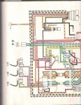
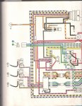
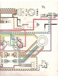
What is the function of Sensor Coil wire “A”, the blue wire? The sensor coil is a $200+ item, maybe I can do without this function and labor? It looks like it is related to the S.L.O.W system. Attached is the wiring diagram (I can only copy in halves.).

Here are the results of the tests the manual calls for the Sensor Coil, using the Ohmmeter and using a Peak Voltage Tester. Terminal “A” failed on both:

Peak Voltage Tests with Digital multimeter and ESI Model 640 DVA Adapter

Sensor Coil Test pg 3-32 - #11 Ground Test – ABCD Passed

Sensor Coil Test pg 3-32 - #11 Output Test – A 0.00, B 1.5v, C 1.78v (spec 0.3v or higher) “A” Failed
Manual says solution is – check condition of wiring, if wiring is good, go to ohmmeter test ( “A” also failed in ohmmeter test)

Ohmmeter Tests

Sensor Coil Test pg 3-33 - #13 - “A” Blue wire Failed OL reading, terminals B&C 12 ohm Passed (all must be 11+-3 ohm)
Sensor Coil Test pg 3-33 - #14 – ABCD Passed no reading (spec - no reading)
 

Attachments

  • photo309336.jpg
    photo309336.jpg
    1.1 MB · Views: 0
  • photo309338.jpg
    photo309338.jpg
    1.1 MB · Views: 0
Last edited:

jakedaawg

Rear Admiral
Joined
Jun 26, 2012
Messages
4,275
K, I'll bite...

what motor and what issues are you having? (Model # please)
 

jakedaawg

Rear Admiral
Joined
Jun 26, 2012
Messages
4,275
Well, in the diagram you pictured "a" is the sensor for the top cylinder...green or "c" would be bottom cylinder and purple would be middle.
 

Klink

Petty Officer 1st Class
Joined
May 27, 2013
Messages
254
The motor is a 1990 70hp Evinrude, 3 cylinder.
It's a long story, but the end result is that the stator had the brown wire crushed, and almost totally corroded away, the brown and yellow was not far behind. Amazingly the engine was still running. When I was doing the ohmmeter and Peak Voltage tests for the stator, I also did the Sensor coil, and found the results I posted. I'm awaiting delivery of a new stator, and so I removed the Sensor coil (0583378 Timer Base Assembly) and found the wires looking brand new, except for the 1" before the Amphenol connector which is not covered by the sleeve and the colors of the wires can't be distinguished (no big deal).

As the tests show, the sensor coil terminal "A" blue wire failed both tests. I wanted to know what that wire does?
 

Klink

Petty Officer 1st Class
Joined
May 27, 2013
Messages
254
Well, in the diagram you pictured "a" is the sensor for the top cylinder...green or "c" would be bottom cylinder and purple would be middle.

I thought that the way one reads the diagram in this case was by aligning the colors that go in and out of the power pack, like the lines I drew into the attached diagram that we are talking about.
 

Attachments

  • photo309357.jpg
    photo309357.jpg
    1.1 MB · Views: 0

jakedaawg

Rear Admiral
Joined
Jun 26, 2012
Messages
4,275
It supplies a small voltage to the scr in the pack basically. Now, someone a will come along and tell you exactly what it does but "in a nutshell" type of saying my answer will hold up. There is a lot of magic smoke in these little boxes and I am not talkative enough to explain it...
 

jakedaawg

Rear Admiral
Joined
Jun 26, 2012
Messages
4,275
I find that these wire diagrams are more often routed for neatness than actual path...
 

Klink

Petty Officer 1st Class
Joined
May 27, 2013
Messages
254
Would I need to replace the whole thing for that one wire?
 

jakedaawg

Rear Admiral
Joined
Jun 26, 2012
Messages
4,275
If it's just the wires that is bad they can be repaired if there is enough good wire next to the pack or timer base to splice into. Amphenol pins are available from any dealer although they are proud of them.
 

Klink

Petty Officer 1st Class
Joined
May 27, 2013
Messages
254
I don't think it is a wire problem, the wires look good, no nicks anywhere. I'll test it with a pin all the way up to see if there is a change.
 

Klink

Petty Officer 1st Class
Joined
May 27, 2013
Messages
254
If it's just the wires that is bad they can be repaired if there is enough good wire next to the pack or timer base to splice into. Amphenol pins are available from any dealer although they are proud of them.

I tested the blue wire "A" all the way up to the timer base and no response, it is all 0L / infinity.
Do I buy a new one just for that one terminal not working?
 

Klink

Petty Officer 1st Class
Joined
May 27, 2013
Messages
254
The motor is a 1990 70hp Evinrude, 3 cylinder.


It's a long story, but the end result is that the stator had the brown wire crushed, and almost totally corroded away, the brown and yellow was not far behind. Amazingly the engine was still running. When I was doing the ohmmeter and Peak Voltage tests for the stator, I also did the Sensor coil, and found the results I posted. I'm awaiting delivery of a new stator, and so I removed the Sensor coil (0583378 Timer Base Assembly) and found the wires looking brand new, except for the 1" before the Amphenol connector which is not covered by the sleeve and the colors of the wires can't be distinguished (no big deal).

As the tests show, the sensor coil terminal "A" blue wire failed both tests. I wanted to know what that wire does?

I received the new stator Evinrude 0584766 (old inventory) and tested it on the bench with an ohmmeter and it failed the ohmmeter charge coil bench test, the only test I can do on the bench:

Charge Coil Test (Stator) Evinrude "ES" 60 thru 70 Service Manual page 3-31 – Test #9 Failed, recorded 402 ohms (specification calls for 480 +-25 ohm). Ohmmeter used is a UEI G2 Phoenix Pro+ DL389 TRMS, not a cheap ohmmeter. Retested it with a cheap analog ohmmeter and got around 400.

Do I return it or install it and do the other tests that require it being mounted to the engine like the he ohmmeter ground tests, and the
Peak Reading Voltmeter test cranking the engine?
 
Last edited:

Klink

Petty Officer 1st Class
Joined
May 27, 2013
Messages
254
P.S. - I also received the new Sensor Coil, and it passed the bench test.
 

Klink

Petty Officer 1st Class
Joined
May 27, 2013
Messages
254
I received the new stator Evinrude 0584766 (old inventory) and tested it on the bench with an ohmmeter and it failed the ohmmeter charge coil bench test, the only test I can do on the bench:

Charge Coil Test (Stator) Evinrude "ES" 60 thru 70 Service Manual page 3-31 – Test #9 Failed, recorded 402 ohms (specification calls for 480 +-25 ohm). Ohmmeter used is a UEI G2 Phoenix Pro+ DL389 TRMS, not a cheap ohmmeter. Retested it with a cheap analog ohmmeter and got around 400.

Do I return it or install it and do the other tests that require it being mounted to the engine like the he ohmmeter ground tests, and the
Peak Reading Voltmeter test cranking the engine?

I installed the stator and tested it on the engine and got no spark whatsoever. Went back and did the same ohmmeter test described in the quote above with the stator mounted on the engine and got 0.405 ohms, that's almost 1/2 an ohm! I must have had the darn multimeter on automatic and assumed it was reading 402 ohms when I table tested it, because I checked this now quite a few times now. The new stator is no good. Will return it and get another one.
 

jakedaawg

Rear Admiral
Joined
Jun 26, 2012
Messages
4,275
If this is a cdi stator make sure all the wires you are testing are correct. Many times I have found them to be in the wrong socket on the plug. If its cdi give them a call, the help you over the phone and are good folks imho.
 

Klink

Petty Officer 1st Class
Joined
May 27, 2013
Messages
254
OK, to update and finalize the thread, I received the second stator, original Evinrude 0584766 new, I bench tested with the ohmmeter and it failed the ohmmeter charge coil test, here are the results:

Charge Coil Test (Stator) Evinrude "ES" 60 thru 70 Service Manual page 3-31 – Test #9 Failed, recorded 393 ohms (specification calls for 480 +-25 ohm). Ohmmeter used is a UEI G2 Phoenix Pro+ DL389 TRMS, not a cheap ohmmeter. Retested it with a cheap analog ohmmeter and got around 380.

I installed the new stator and it got 389 ohms. It passed the other ohmmeter test to see if it has any grounds. I went straight to the spark test and it jumped the 7/16" gap on my home made 8 cylinder distributor cap setup, strong spark. So I did a Synch & Link, and Max Spark Advance check, and all is good now.
 
Top