1971 100 hp johnson wont shut off

thelegion

Seaman Apprentice
Joined
Aug 8, 2017
Messages
47
so here is the problem,

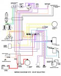
I replaced the rectifier, started the motor and now it won't shut off, it will if I pull one of the rectifier leads off the buss bar. The master power switch has no effect as well. When running the batteries seem to be charging @ 12.5-7 volts, there is a fuse on the engine (20 amp) that has no effect when pulled, before the rectifier was replaced I could pull the fuse and the motor would stop.

I have a shop manual and wiring diagram but all seems to be correct, could the key switch have just packed it in? I'm at a loss and any thoughts would be welcomed.

cheers
 

jbuote

Lieutenant Junior Grade
Joined
Aug 17, 2016
Messages
1,001
Deleted incorrect information.....
 
Last edited:

oldboat1

Fleet Admiral
Joined
Apr 3, 2002
Messages
9,607
It doesn't sound like the battery is charging -- not sure if the engine should quit when pulling off a rectifier wire, but there is a chance that disconnection with the engine running could blow a diode.

Check or replace the fuse.
 

boobie

Supreme Mariner
Joined
Nov 5, 2009
Messages
20,826
The "M" terminals on the ignition switch have nothing to do with the ignition on the 71 100 hp as it's battery ignition.
 

jbuote

Lieutenant Junior Grade
Joined
Aug 17, 2016
Messages
1,001
Ahh..
​Thanks boobie.. I've deleted the incorrect information..

My apologies all..
 

thelegion

Seaman Apprentice
Joined
Aug 8, 2017
Messages
47
It doesn't sound like the battery is charging -- not sure if the engine should quit when pulling off a rectifier wire, but there is a chance that disconnection with the engine running could blow a diode.

Check or replace the fuse.

ok I need co clarify a bit I guess,
I did pull the rectifier wire but it was connected to the stator wire and when they separated the motor quit,
 

oldboat1

Fleet Admiral
Joined
Apr 3, 2002
Messages
9,607
Replace the fuse first. The rectifier has a couple of yellow wires and a red one -- that the one you used? I assume you replaced the rectifier because the battery wasn't charging (suggesting that wasn't corrected, or the new rectifier was damaged when disconnected with the motor running -- believe the red wire would be the critical one). They would be connected to the stator coils at the terminal block (Rectifier converts A/C to D/C, as you probably know).
 

thelegion

Seaman Apprentice
Joined
Aug 8, 2017
Messages
47
Replace the fuse first. The rectifier has a couple of yellow wires and a red one -- that the one you used? I assume you replaced the rectifier because the battery wasn't charging (suggesting that wasn't corrected, or the new rectifier was damaged when disconnected with the motor running -- believe the red wire would be the critical one). They would be connected to the stator coils at the terminal block (Rectifier converts A/C to D/C, as you probably know).

yes the yellow are connected to the (rectifier/stator wires ) and the red ends up going to the solenoid, and the fuse is good. I've studied the wiring diagram for hrs and the only thing I can come up with is the key switch just failed, but whats the chances of it failing after the rectifier was replaced. And to make it more confusing when I turn the master switch off the motor still runs as before with the bad rectifier it would still turn off.
 

F_R

Supreme Mariner
Joined
Jul 7, 2006
Messages
28,195
Easy. The blocking diode (between the key switch and shift switch) is blown. That's exactly what it's there for.

BTW, avoid disconnecting those rectifier wires while running. That'll blow the rectifier.
 

thelegion

Seaman Apprentice
Joined
Aug 8, 2017
Messages
47
Easy. The blocking diode (between the key switch and shift switch) is blown. That's exactly what it's there for.

BTW, avoid disconnecting those rectifier wires while running. That'll blow the rectifier.

Thank you,
I'll give it a go today and test the diode, now just to make sure we're on the same page; it's the diode that hangs off the rear of the motor between the two stator wires? (big ball of epoxy with wires)??

(edit) So in the wiring diagram I see another diode in the control box which I gather now is the one your talking about. Now the question is; it's gonna be very difficult to find a replacement I imagine, so I guess I'll be making one (not difficult) but I will have to guess at the resistance as I can't find any reference to diode values.

cheers...
 
Last edited:

Joe Reeves

Supreme Mariner
Joined
Feb 24, 2002
Messages
13,262
You need to pay closer attention to F_R..... He said "(between the key switch and shift switch)"..... that's nowhere near the engine! :)
 

F_R

Supreme Mariner
Joined
Jul 7, 2006
Messages
28,195
In the remote control. It prevents the alternator from continuing to feed the ignition when you turn the key off. Assuming you have the stock side mount control that came with the motor it is part number 0279176 from an Evinrude dealer or CDI part number 953-9176 from iboats.

In theory, it has to carry somewhere around 6 Amps at up to around 16 Volts. But it is an inductive load, so the requirements are higher. Furthermore, when selecting diodes, always go at least double the theory requirements. So draw some numbers out of the air, and get 15 A @ 50 V as a minimum. More does not hurt, and can be more reliable.
 

thelegion

Seaman Apprentice
Joined
Aug 8, 2017
Messages
47
GREAT, ;)

Thank you so much for the expertise,

I've had to completely re-wire the boat and re-invent the steering and it's been a real learning experience. Every time I go into the local parts store they roll their eyes at me and smile, but I've had the motor running and it scoots on my 16.5 Campion centre console. It's a clean motor and I can't bear the thought of tossing it for a new one and besides how do you learn to fix things.

As soon as my local electronics shop opens I enquire about the diode, I'll post the results when I get it done; I'm sure this will help someone in the future.

thanks, TL.

(quick update)

just tested the diode and yes it's "pooched"
 
Last edited:

F_R

Supreme Mariner
Joined
Jul 7, 2006
Messages
28,195
No Title

I know this is not the correct diagram for your motor, but I'm posting it because it shows the polarity of all those diodes we've been discussing.
 

Attachments

  • photo241822.jpg
    photo241822.jpg
    253.2 KB · Views: 0

thelegion

Seaman Apprentice
Joined
Aug 8, 2017
Messages
47
Great diagram, shows how many diode's and the current direction.

thank you,
TL.
 

thelegion

Seaman Apprentice
Joined
Aug 8, 2017
Messages
47
No Title
 

Attachments

  • photo278456.jpg
    photo278456.jpg
    83.2 KB · Views: 0
  • photo278457.jpg
    photo278457.jpg
    101.9 KB · Views: 0

thelegion

Seaman Apprentice
Joined
Aug 8, 2017
Messages
47
I tested the Monkey and so far it's good, but I built a spare just incase; I'll put this one in tomorrow.

Again, thanks for the wiring diagram and the knowledge.
TL...:adoration:
 
Top