1989 force 125hp tachometer issue(veethree)

puffitu

Chief Petty Officer
Joined
Dec 30, 2018
Messages
555
Forgot to mention that the whole thing (I think) happened because my stater solenoid ground post was lose. Couldn’t start the motor so I jumped the starter to get it back to the dock. That’s when I noticed the circuit breaker tripped and tach pegged
 

The Force power

Commander
Joined
Feb 3, 2019
Messages
2,250
Forgot to mention that the whole thing (I think) happened because my starter solenoid ground post was lose. Couldn’t start the motor so I jumped the starter

How did you "jump" the Starter? across the POS. terminal on the Solenoid? OR supplied power from the POS. wire of the Solenoid to the Starter?
 

jerryjerry05

Supreme Mariner
Joined
May 7, 2008
Messages
17,926
A pair of plyers across the big lugs of the solenoid.
That should make it turn.
If not then a test light will tell you a lot.
 

puffitu

Chief Petty Officer
Joined
Dec 30, 2018
Messages
555
Hey yall
So after I was able to get a new tach and temp gages installed, the temp gage works perfectly but the tach only works for a few seconds after starting the engine. It comes on and after like three or four seconds fades down to zero and stays there. now, is I shut the engine off and start again it does the same thing. ??? What could cause this?? Ive verified the rectifier is working and checked for breaks in the sender wire as well as all other connections...Stator output maybe??
 

puffitu

Chief Petty Officer
Joined
Dec 30, 2018
Messages
555
Ive got a test light, ohm meter, dva so id appreciate a test procedure for dummies if anyones got some
 

GA_Boater

Honorary Moderator Emeritus
Joined
May 24, 2011
Messages
49,038
This problem isn't a mismatch between the number of stator poles and tach setting. That would cause either a high or low tach, not work for a few seconds and quit.

How did you verify a working rectifier?
 

puffitu

Chief Petty Officer
Joined
Dec 30, 2018
Messages
555
CDI troubleshooting page. Continuity one way and not the other-taken between G to both ac posts and RED to both ac posts and vise versa. The rectifier isn't the issue as I have four so I even swapped them out - the tach still does come on but just after I start the engine then a second or two later falls to zero. Ive checked all possible things I could think of; sender wire, all ground and hot connections . Connectors have all been replaced under the hood.All I need to do is to put a test light on the stator wires when running but hadn't had a chance yet. In my little brain; its telling me that stator may be the issue but Im not certain.
 

GA_Boater

Honorary Moderator Emeritus
Joined
May 24, 2011
Messages
49,038
Why don't you connect the meter across the battery and see if the voltage increases or stays the same as the motor RPM is raised to a fast idle?
 

puffitu

Chief Petty Officer
Joined
Dec 30, 2018
Messages
555
What would cause this ? I did notice and over charging prior to the tachometer stopping working -Note the resistor between ignition and send post.
 

Attachments

  • photo324544.jpg
    photo324544.jpg
    2.1 MB · Views: 1

The Force power

Commander
Joined
Feb 3, 2019
Messages
2,250
Is that the same pic. as in post #13? Maybe caused by high voltage 16 to 19 or more volts?
Before installing a new one, ensure voltage input does not exceed 14.5 V
Like I said in earlier post; one thing may of let to another, sorry just guessing here
 

GA_Boater

Honorary Moderator Emeritus
Joined
May 24, 2011
Messages
49,038
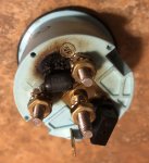
Heat. A resistor dissipates power as heat. I don't know why a resistor is between I, which is 12 volts from the Ignition, and S, which is the AC signal from the stator, rectifier or power pack if you have one. Regardless of the source for S, it does comes from the stator, either from a rectifier or power pack connection.

Let's stop guessing. Hook up a meter on the AC scale to the S stud and the other lead to the ground stud, the one with the metal strip. Start the motor and see what AC voltage is shown and does it start high and drop off?

And do the earlier DC measurement across the battery. What are you seeing there?

One other thing - Did you replace the tach with the same brand and model? Did you transfer the resistor to the new tach? Did the new tach come with any instructions about a resistor?
 

puffitu

Chief Petty Officer
Joined
Dec 30, 2018
Messages
555
The resister was on the Temp gage between I and S studs. I’ve since replaced two gages; the Tach and the Temp gage which by the way did not come with a funky resistor. The old temp gage resistor was melted fried so no I did not install on new gage. Tests performed are. Battery voltage while throttling,rectifier outputs we’re tested (ohms directional as well as running), it’s charging. Checked sender wire fo breaks seems ok and getting signal but haven’t checked if fluctuating wi throttle. My step dad works at Veethree in Bradenton FL so he gets these for me but he knows less about the makeup and functionality than me and I’m pretty limited when it comes to electronics and or test equipment.
 

GA_Boater

Honorary Moderator Emeritus
Joined
May 24, 2011
Messages
49,038
So you had two fried resistors? One on the temp gauge and one on the tach?
 

puffitu

Chief Petty Officer
Joined
Dec 30, 2018
Messages
555
No -the resistor was only on the temp gage in the picture; I’ve since replaced it with a new one( didn’t come with a resistor this time).
 

sam am I

Commander
Joined
Jun 26, 2013
Messages
2,169
https://maxrules.com/graphics/force/...thru89_eng.jpg

https://maxrules.com/graphics/force/wiring/120HP_thru91b_eng.jpg


As far as I found and referring to the above info, your engine isn't necessarily stock?

If by chance then while mod'ing this thing and hooking a temp gauge (with a resistor tied from I to S) to a over heat "thermal switch" shouldn't work too well in that......

A) The gauge isn't made for this, it requires a 30-450 (46-1200 for cylinder head temp) ohms water temp sender
B) That resistor gets tied....
  • With a thermal switch: From I (12-18V) to S (ground) if the switch closes, hence all the smoke, fire charring and fogging up.
  • With a standard sender: From I (12-18V) through S (30-450/46-1200 ohms) to ground, hence all the smoke, fire charring and fogging up.
Either way........that setup isn't standard but, sounds like you've since removed the resistor by getting a new gauge so, perhaps moot point now?

The tach however I wondering about, should be fine hooked to the stators feed (purple or gray?) wire, you say it just moves for a second then drops to zero? Is this when just powered up/Ig. switched on? If so, sound like its just getting power and no sig......Double check the sig feed path.
 
Last edited:
Top