1991 Force 90hp wiring and timing

tavacska

Petty Officer 1st Class
Joined
Jan 21, 2017
Messages
244
I just got a 1991 Force 90 HP with prestolite ignition. Someone must have messed up the wiring. I find out a wiring diagram online but still confused and a lot questions.

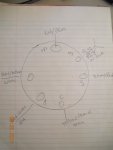
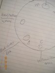
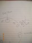
1. For the key switch, B comes from battery positive. C goes to choke. I is overheat buzzer. But what is M? The two M lined together at no-turn position, but disconnected and doesn't link to any other lines when turn to I and II position. The white lines goes to CD module, which I found out to be black/yellow lines actually. These lines come from Key-M - StopSwitch - Key-M - Blue - Black - Purple - Stator? Are these lines, which connected to CD modules, the +12V or Ground in the end?

2. How is the over heat Buzzer connected, I have no idea at all.

3. For outboard timing, is it true that the starter crank timing is 28 BTDC? Mine is now checked to be around TDC. If it should be 28 BTDC, the timing will increase to 30-32 BTDC when WOT? Only 4 degree? I have a distributor mercury outboard too, which idle timing is 4-6 BTDC and 21 BTDC at WOT. These statement for Force really confuses me.

4. For WOT timing check at garage, can I manually slowly crank and get sparks, just like what we do with distributor motor?

Thanks.
125HP_thru89_eng.jpg
 

Attachments

  • Chry55_82_84.gif
    Chry55_82_84.gif
    16.3 KB · Views: 8

Nordin

Commander
Joined
Jun 12, 2010
Messages
2,434
The M termials at keyswitch is the stop circuit. In OFF position the M termials as continuity to each other.In IGNITION and position START it is open.
White wirer from CD module goes to one of the M terminals and the other M terminal has a blue wirer which goes to terminal stripe and grounds out there.

Thermo buzzer is connected with a +12V power wirer at one terminal and the other terminal are connected to the thermo switch which is a bimetal switch which goes to ground when temperature are going to high.

You set the timing static at 28dgr BTDC at cranking speed. It gives you about 32dgr BTDC at WOT.

You can set the timing dynamic with a timing light to 30-32 dgr BTDC, BUT you need an assitant how drives the boat when checking.

Timing advance can be way different depending on brand. It depends on compression ratio, charging system and port timing.

Yes you can crank at garage and check with a timing light at the flywheel and timing plate.
 

Nordin

Commander
Joined
Jun 12, 2010
Messages
2,434
Forgott to mention that you have to have the throttle at WOT when setting static timing 28 dgr at cranking speed.
This will give you about 30-32 drg running at WOT.
 

jerryjerry05

Supreme Mariner
Joined
May 7, 2008
Messages
17,926
This might help??

The overheat: it gets wired into about any key activated power lead.
The buzzer can be wired wrong, so test it by swapping the leads.
 

Attachments

  • photo305818.jpg
    photo305818.jpg
    777.9 KB · Views: 4
  • photo305818.jpg
    photo305818.jpg
    777.9 KB · Views: 2
  • photo305819.jpg
    photo305819.jpg
    760.1 KB · Views: 3
  • photo305820.jpg
    photo305820.jpg
    743.7 KB · Views: 2

tavacska

Petty Officer 1st Class
Joined
Jan 21, 2017
Messages
244
Forgott to mention that you have to have the throttle at WOT when setting static timing 28 dgr at cranking speed.
This will give you about 30-32 drg running at WOT.

That explains well the timing for me.

When I did on mercury, it's always 4-6 BTDC around idle and 21 at WOT.

So for Force, it's 28 BTDC at WOT (cranking), 32 BTDC running at WOT.
But at idle or neutral, it's still around TDC.

I tested only neutral timing yesterday, and it's around TDC. I will leave timing alone and start from there.
Because in 1991 90 force, the timing has no adjusting screw but only a adjusting nut on the inside part, which is hard to reach. I believe the previous owner won't bother to mess with the timing.

Thank you.
 

tavacska

Petty Officer 1st Class
Joined
Jan 21, 2017
Messages
244
This might help??

The overheat: it gets wired into about any key activated power lead.
The buzzer can be wired wrong, so test it by swapping the leads.

Thanks, that explains me the buzzer right now. So if the thermal switch alarms, it will become continuous, the buzzer will buzz.
 

tavacska

Petty Officer 1st Class
Joined
Jan 21, 2017
Messages
244
Right now, the control cable is not the original, the colors do not match either on control cable or some wires on motor. So I have to trace wires one by one to make a note on them.
I will have to buy a 16 gauge x 10 soow wire as the remote control cable.

These are only for testing, not on water running.
1. I don't have a buzzer right now. So I will leave key-I open, no connecting at all.
2. I don't connect to a stop switch right now. For testing, the white from CD module will be connected directly to a ground. So no connecting to Ms at all.
3. On stripe bar under the buzzer in the diagram, does that mean the black and purple all grounded directly? But the red/blue and orange are not grounded but connected to buzzer separately?
4. B to power +, C to stroke, S to starter solenoid.
5. With such connecting, I put key to IGNITION position. And then I turn the cranking wheel clockwise by hands. Will I see sparks on the spark plugs?
 

tavacska

Petty Officer 1st Class
Joined
Jan 21, 2017
Messages
244
2. I don't connect to a stop switch right now. For testing, the white from CD module will be connected directly to a ground. So no connecting to Ms at all.

Just figured out it is a wrong statement.
The CD module white lines should be left open in normal operation. It is shorted at stop switch when in trouble and grounded so no spark anymore when the stop switch is triggered.
 

tavacska

Petty Officer 1st Class
Joined
Jan 21, 2017
Messages
244
I have a mercury 1977 1150 top mount control box. Can it be used for this force motor?
Anyone has suggestion for the top mount control box?
 

Nordin

Commander
Joined
Jun 12, 2010
Messages
2,434
I will suggest you to not touch the timing yet, just check the timing with a timing light at cranking speed.
The timing does not change as long as you do not change trigger or the stop/set rod/screw come loose.

If you check the timing running at WOT retard it to 30 dgr if it is at 32 dgr. You will not see any different in performance but the engine will feel better and last longer at 30 dgr.
The fuel of today has a lot of additives and are worse then before when these engines were engineered.

When checking for spark at cranking you need to do it with the starter motor. Turning by hand will not produce any spark because the ignition system need at least 200 rpm to energize the system.
Maybe you can do it by a rope but I would do it with the starter.

The Mercury remote control will not fit with the Mercury connectors at the end of the wires.
Chrysler/Force use a different typ. The remote control it self will fit.
 

Nordin

Commander
Joined
Jun 12, 2010
Messages
2,434
I will suggest you to not touch the timing yet, just check the timing with a timing light at cranking speed.
The timing does not change as long as you do not change trigger or the stop/set rod/screw come loose.

If you check the timing running at WOT retard it to 30 dgr if it is at 32 dgr. You will not see any different in performance but the engine will feel better and last longer at 30 dgr.
The fuel of today has a lot of additives and are worse then before when these engines were engineered.

When checking for spark at cranking you need to do it with the starter motor. Turning by hand will not produce any spark because the ignition system need at least 200 rpm to energize the system.
Maybe you can do it by a rope but I would do it with the starter.

A distributor system as older Mercs and Chrysler/Force are powered by the battery but the Prestolite system has magnets in the flywheel and are self enegized, but it need speed from the flywheel to induce power to the capacitors in the CD box.

The Mercury remote control will not fit with the Mercury connectors at the end of the wires.
Chrysler/Force use a different typ. The remote control it self will fit.
 

jerryjerry05

Supreme Mariner
Joined
May 7, 2008
Messages
17,926
I'm guessing your not in the US???
Maybe fill out a signature and tell us where your from and some details about your boat/motor.

What boat?? sometimes the manufacturer has wiring diagrams for your boat, all
you have to do is ask??

Don't touch the timing.
Nothing but trouble there, unless you understand the procedures for setting.
There are some good video's out there that show how it's done.
The first 4 post in this forum have tips and tricks and procedures for some repairs.

The wiring harness for a Mercury can be used but the color code will be a problem.
Like Nordin said, the control box/shifter won't work.

No buzzer: a 12v car, motorcycle horn will work, just make sure it's not wired backwards.

They sell shifters and wiring harnesses on e-bay.
There is nothing like the right equipment to make the job go right:)
 

tavacska

Petty Officer 1st Class
Joined
Jan 21, 2017
Messages
244
Thanks for the good information. The self-energizing mechanism is quite different with the distributor one.
I am in Texas with a 77 Boston whaler Newport.

I started the motor yesterday. Very easy start and very smooth running. Solid engine sound, fresh water use only from a pontoon boat. But it can not stop running because I didn't connect the M-M pole in key switch. Fortunately, it only runs around 1000-1500 rpm and I have to pull the fuel line to let her stop. Now I come to realize how to connect the M poles.

The top of engine was connected with a check port plug and the water shoots out very far, which I have to replace with a stainless screw.

So far so good. I will post a picture of the old remote control with the engine to see if I can switch side from right to left, because I want it to be installed on the right side of the center console.
 

jerryjerry05

Supreme Mariner
Joined
May 7, 2008
Messages
17,926
The hole on top, it can be used as a tell tale.
Buy a brass elbow and run a hose through the lower cowl.
Home Depot has rubber bushing for the hole you drill in the cowl.


Being as the motor came from a pontoon, you'll need a different prop.
Tons need a much lower pitch prop compared to a Whaler.
You need something like a 17p maybe a 19p depending on the length/weight of the boat.

Sea Star shifters.
MT-3-Controls
http://www.seastarsolutions.com/wp-...MT-3-Control-CH5300-5310-Rev.2-055001-578.pdf

This is a new top mount single lever shifter.
Bad thing is the trim isn't on the handle:(

SL-3 top mount single lever.
This has the trim
http://www.seastarsolutions.com/wp-content/uploads/2018/05/212442_r0.pdf

Good luck.
 

tavacska

Petty Officer 1st Class
Joined
Jan 21, 2017
Messages
244
Thanks, Jerry.

Now I have encountered a difficult choice for me to make.

My boat is the 1977 boston whaler newport 17 feet with a 1977 Mercury inline 6 1150 with good compressing.
Basically, I have almost changed everything on the Mercury so far. CD, coil, distributor trigger, solenoid, starter, trim motor, a piston, all rings, upper and lower crankshaft seal, check valves, carburetor rebuilt, fuel pump rebuilt, all the gaskets.

Now it idles very good but still suffers the water intruding. I have changed the exhaust cover and gaskets but I believe it's the inner plate leaking actually. Every time I fix it I thought it would be the last step. Since I have devoted so much effort in it and the new gasket for leaking is on the way. Let's say if the fix is final is done and good running, which one should I choose? The 77 mercury with most changing brand new or this force test good solid idling?
 

Nordin

Commander
Joined
Jun 12, 2010
Messages
2,434
I am a Mercury fan and have a 1972 Mercury 800 80Hp 4 cylinder on my boat.
Runs like a champ,. smooth, BUT the Mercurys are difficult to troubleshoot,
Chrysler/Force much easier.
In that case I would suggest the Force.

The 6 inline Merc has more power.

About the water intrusion, the Merc from that age has no head.
The whole cylinder block is cast in one piece, check the gasket and the plug thread at the water jacket cover that looks like a head.
It is not a head just a cover of the water jacket.
 

tavacska

Petty Officer 1st Class
Joined
Jan 21, 2017
Messages
244
About the water intrusion, the Merc from that age has no head.
The whole cylinder block is cast in one piece, check the gasket and the plug thread at the water jacket cover that looks like a head.
It is not a head just a cover of the water jacket.

Nordin, the #5, and #6 both have thin milky cover on the spark plugs. I check the exhaust from under when I lift up the powerhead, it's like the dark brown milky gunk everywhere inside the exhaust. I thought the water leak happened somewhere in the exhaust part and then be sucked in the cylinders. That's why the engine idles still pretty good. There is no water showing up at the plugs when the motor is running.
 

Nordin

Commander
Joined
Jun 12, 2010
Messages
2,434
As I see in your post you have changed the lower crank seal which could be the issue, but then the only things that can cause this are bad gasket at exhaust cover plate or a crack/hole in the plate that fits against the block, leak at water jacket cover at the head and a crack somewhere in the block around #5 and #6 cylinder.

Start with exhaust cover plate BUT be careful the screws holding it are easy to snap.
Then check the "head" cover, if all of that looks good then there might be a crack in the block.

Hopefully not.
 

jerryjerry05

Supreme Mariner
Joined
May 7, 2008
Messages
17,926
Had a similar problem with a 50Merc.
But it was flooding with gas, not water.
Finally, complete dismantle and found a hairline crack on the intake side of the block.
Was so small it looked like a scratch.
It was about as old as your motor too.

The brown goo shows it's been leaking for a while.
Could very well be the 3gaskets or the baffle plate.
Like Nordin said use extreme caution when removing the screws.
 

tavacska

Petty Officer 1st Class
Joined
Jan 21, 2017
Messages
244
Had a similar problem with a 50Merc.
But it was flooding with gas, not water.

Actually, I am more interested in the gas flooding.
The 77 mercury has a line from lower intake to the gas pump. When I replaced the check valve, I have to pull the line from the lower intake, guess what, the milky get out from there. I don't know it's water or gas there.
A Johnson guy also found the milky gunk from the balance tube, exactly the same as what I found in exhaust. His problem turns out to be bad carburetors. So right now, I still try to figure out where I should check first.

I have replaced the exhaust cover plate and baffle plate, and the gaskets, twice. The only gasket I didn't change is the inner plate gasket.
 
Top