Electrical Problems

mercnewbie

Cadet
Joined
Jun 29, 2011
Messages
14
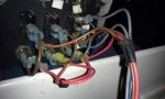
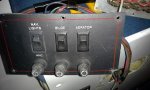
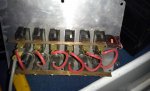
Hi everyone, I'm trying to change my fuse panel but somehow it does not seem to work. I wonder if someone could explain to me how this is suppose to be wired up. On the old panel, I only have Bilge, Aerator, Nav. Lights. The new panel has more options to offer but I need to get the three going first before anything else. I'm including pictures since explaining it to friends did not work (lol). With the existing panel, all switches have two wires going to the battery, one for positive and one for the negative then we control from the switch. So I have a bunch of wires taped up to a booster cable type clamp and have to put them on and off every time. So the question is how can I wire up the multi panel versus the older 3 switch. Thanks in advance for any help you can give me.
 

Attachments

  • photo223676.jpg
    photo223676.jpg
    25.3 KB · Views: 0
  • photo223677.jpg
    photo223677.jpg
    19.9 KB · Views: 0
  • photo223678.jpg
    photo223678.jpg
    23.2 KB · Views: 0
Last edited by a moderator:

gm280

Supreme Mariner
Joined
Jun 26, 2011
Messages
14,590
First picture mean nothing to me, second picture shows the three switches you want to get working first on the new panel, I assume. However the third picture leaves me scratching my head. Reason? Because it seem you have a buss bar across the switches and the other part of each switch goes to an individual fuses. And that is okay if you are using that buss bar as the positive input. But then you have another buss bar on the other leg of all the fuses all ganged together again. So in essence you have one switch now, not six individual switches because of the two buss bars... I think you should sit down and draw out how each switch should be wired from the positive input from the battery or positive buss bar to the fuse and then to each switch to the assessory you want to control. If that means six individual pieces of paper (one for each switch circuit) then so be it if that helps you from getting confused. Take the very first switch. Let's use the bilge pump as an example. Take the positive wire to one terminal of one of the fuses. The other terminal of the fuse should go to the switch. The other terminal of the switch then goes out to the pump. The ground from that pump goes back to a ground buss bar connected to the negative side of the battery. And that is one circuit wired up already. Then just follow that same scenario for all the other circuit you want to wire. But look at each switch like one individual circuit and that will illuminate confusion with all the wires...
 

Grandad

Lieutenant Commander
Joined
Jun 7, 2011
Messages
1,504
Hi mercnewbie. I'm scratching my head about the same issue with picture 3 as gm280 is. This panel looks to be a custom made work-in-progress. Obviously the switches were installed through the cover plate before those brass bus bars were soldered (?) into place. Without more switch detail, I can't tell whether that bar should be removed or if it is a common negative buss for indicator lights on each switch. - Grandad
 

StingrayMike

Petty Officer 1st Class
Joined
Aug 17, 2014
Messages
355
Looks like the top buss bar is on the normally closed contacts when the switches are off.
maybe used to provide more support for the switches? Not sure why, or feeds to the negative to the battery when the switch is off
test the switches with a multimeter and more likely put your wire for your load on the other spade tab
 

Silvertip

Supreme Mariner
Joined
Sep 22, 2003
Messages
28,758
This panel is just a seriously mis-engineered custom panel. Here is what "should" be done:

1) The bottom bus bar is an attempt to provide bulk +12 volts to all circuits. However, the gray wire (assuming that's the supply) should connect to the bottom buss bar, not one of the switches. But since the switch was likely intended to be a "Master" power switch, the gray wire is ok where it is, but then the "load" side of the switch needs to connect to the bottom buss bar so power first feeds all of the fuses and then passes from each fuse to each switch. As it is, when turned on it is simply back feeding every circuit so regardless what or where an item is connected, it will be on regardless what switch is used.
2) The red wires from each fuse to each switch is done correctly.
3) The top bus bar MUST be removed as it serves no useful purpose unless the switches are lighted. If this is the case, then that bus bar must connect the ground for the internal light to ground.
4) I have no idea what the black mess is at the right end of the top bus bar. (Ground connection perhaps).
5) There is an empty terminal on each switch directly below the red wire. Those are the "load" connections that feeds +12 volts to whatever device that switch controls.
6) The ground from each device does NOT connect to the ground bus for internal lights on the switch -- they go to the boat ground buss or back to the negative terminal of the battery.
 
Top