Help with dash board wiring

Larry E

Petty Officer 2nd Class
Joined
Jan 1, 2012
Messages
161
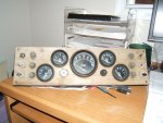
I am presently restoring a 1974 Seaswirl Ranger with OMC and GM 2.5 motor. Prior to me buying the boat someone tried to rewire the dash board and did not get things back where they were. Would it be possible for someone reading this to take a picture of the wiring on the back of the dash if you have the same setup as mine?

Very much appreciated if you can help.
Larry E
 

Attachments

  • Instrument panel before 001.jpg
    Instrument panel before 001.jpg
    143 KB · Views: 0

Bondo

Moderator
Staff member
Joined
Apr 17, 2002
Messages
70,525
Re: Help with dash board wiring

Ayuh,... Welcome Aboard Larry,...

At the top of this forum are stickies, with wiring diagrams,...
There's some there, that'll cover yer dash...
 

Larry E

Petty Officer 2nd Class
Joined
Jan 1, 2012
Messages
161
Re: Help with dash board wiring

Looking for the stickies but cannot find
Ayuh,... Welcome Aboard Larry,...

At the top of this forum are stickies, with wiring diagrams,...
There's some there, that'll cover yer dash...
 

Larry E

Petty Officer 2nd Class
Joined
Jan 1, 2012
Messages
161
Re: Help with dash board wiring

Did not find anything that would help me with my issues. I need a good diagram or picture of the wiring for the ignition switch. Also the diagram in the OMC book shows a yellow/red wire to the switch but the harness has no such color wire in it.

At the top of the Electrical "Forum" not the top of this page. At the very top of the page you'll see "stickies"

Go here: http://forums.iboats.com/forumdisplay.php?f=23
 

Silvertip

Supreme Mariner
Joined
Sep 22, 2003
Messages
28,762
Re: Help with dash board wiring

I guess you should have asked for ignitiion switch wiring then huh! Look at the back of your ignitiion switch. It will have letters nexdt to the switch terminals. B = Battery. That has +12 volts on it from the engine harness. I = Ignitiion. That wire is hot when the key is turned to the RUN position. That wire is what energizes the ignition back at the engine. S = Start. That wire has 12 volts on it when the key is turned to START. That energizes the starter solenoid back at the engine. To identify the S wire at the engine look at the small terminal on the starteer solenoid. The B wire should be hot all the time (provided you have a battery in the boat). If you need gauge wiring, go back to the stickies. Those diagrams are pretty representative of boats like yours.
 

Larry E

Petty Officer 2nd Class
Joined
Jan 1, 2012
Messages
161
Re: Help with dash board wiring

Thanks very much. No wonder they call you "Supreme Mariner"...:)
 

Larry E

Petty Officer 2nd Class
Joined
Jan 1, 2012
Messages
161
Re: Help with dash board wiring

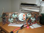
Instrument panel before 002.jpgOne last question regarding this dilema. I understand what each terminal is for now could you tell me what colored wires go where? That is the crux of the matter. Also every wiring diagram I have seen calls for a "yellow/red stripe" wire from starting switch to solenoid. My wire harness does not have this wire in it. The attachment shows what I have now. The reason I am working on this is that I can cross over on the starter solenoid and the starter works. Plug in the dash and turn the key and nothing works. So before I start replacing items like the ignition switch and so I want to make sure the wiring is correct. Here are the colored wires I have coming out of the harness to the dash.

red
blue
black
tan
white
purple
grey


Thanks again for your patience and input
Larry E
 
Last edited:

Silvertip

Supreme Mariner
Joined
Sep 22, 2003
Messages
28,762
Re: Help with dash board wiring

You really need to start with the boat side harness and identify what the wire colors are and what they are for. I explained how to identify the Start solenoid (S) and battery (B) and ignition (I) wires. Whatever the color is at the engine must mate up with whatever color the wire is from the applicable terminal on the ignition switch. Electricity doesn't care what color the wire is. Just mate them up end-to-end. Unless you have a diagram for your specific boat you won't know what those colors are. Your only option is to trace them. The other wires in the dash harness work the same way but you have the advantage of having the diagrams in the stickies to help you. Dash wiring for the gauges is very standard. But get the ignition worked out first. As shown in the diagrams, every gauge except the speedometer requires +12 volts when the key is on. The wiring is such that the +12 volt terminal on each gauge is daisy chained to the next one. That power comes from the "I" terminal on the switch. Every gauge(even the tach) requires ground. Those connections run in daisy chain fashion to wherever ground is on your boat. Each gauge has an internal light. The +12 volt feed for the bulbs is again daisy chained to the NAV/ANCHOR light switch. The voltmeter (if you have one) should now work with those three connections. The tach, oil pressure, water temp, and trim gauge all have a sender "S" terminal so there will be one wire from each sender at the engine that goes to the respective gauge. The fuel gauge sender is normally pink. But you can identify each wire by looking at the appropriate sender. Again, it doesn't matter what color the wire is at the dash. Just match them up.
 

Larry E

Petty Officer 2nd Class
Joined
Jan 1, 2012
Messages
161
Re: Help with dash board wiring

OK I'll be back... By the way if anyone here knows of a wiring diagram for a 1974 seaswirl 16ft Ranger that would help a lot.

Larry E
 

Larry E

Petty Officer 2nd Class
Joined
Jan 1, 2012
Messages
161
Seaswirl manual

Seaswirl manual

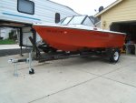
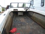
I am restoring a 16ft 1974 Seaswirl Ranger and need to find a manual or a wiring diagram for the boat. Any ideas?

Thanks
Larry ETrailer restoration.jpgBoat progress 9-17-11 001.jpg
 

Woodonglass

Supreme Mariner
Joined
Dec 29, 2009
Messages
25,924
Re: Seaswirl manual

Re: Seaswirl manual

Welcome to iBoats!

Typically Boats do/did not come with manuals other than just general maintenance manuals. As for wiring this will give you a basic idea for all boats...

Console%20Wiring.gif
 

Larry E

Petty Officer 2nd Class
Joined
Jan 1, 2012
Messages
161
Re: Seaswirl manual

Re: Seaswirl manual

Thanks much I will add that to my collection of diagrams...:redface:

Larry E
 

Silvertip

Supreme Mariner
Joined
Sep 22, 2003
Messages
28,762
Re: Seaswirl manual

Re: Seaswirl manual

Welcome to iBoats!

Typically Boats do/did not come with manuals other than just general maintenance manuals. As for wiring this will give you a basic idea for all boats...

Console%20Wiring.gif

This diagram is nicely done but it does not represent a "typical" recreational boat. Your diagram is very incorrect in that you show +12 volts going directly to the instruments and to the switches. You also show negative leads going to the negative buss from the switches. That will create direct shorts when the switches are closed. All instruments normally get power from the ignition switch so they are active only when the key is in the RUN position. On outboards that is the "A" (accessory) terminal on the switch. On I/O's that's the "I" (ignition) terminal. If all of the ground connections on the switches are for the indicator light in each switch and your intent was to not show the device each switch controlled, then the ground connections are ok. Even then, that ground connection on each switch should ground only the indicator. They are not intended to be part of a general ground system for everything on the console. No disrespect here but this is a misleading diagram and not representative of general console wiring.
 

Woodonglass

Supreme Mariner
Joined
Dec 29, 2009
Messages
25,924
Re: Seaswirl manual

Re: Seaswirl manual

I stand corrected. Having re-read your response to an iBoater two years ago,http://forums.iboats.com/showthread.php?t=310696
I see where you stated his diagram was Ok, but then further on went on to correct that and state in fact it was not. Sorry for the confusion.
I think this diagram correctly reflects how you are recommending the wiring should be done from the Ignition and switches.


11666d1172161592-typical-wiring-schematic-diagram-instrumentpanelwiring.jpg
 

Larry E

Petty Officer 2nd Class
Joined
Jan 1, 2012
Messages
161
Re: Seaswirl manual

Re: Seaswirl manual

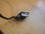
Neutral Switch.jpg
As wired from the factory.

This was a great help...Now I am suspecting I have a bad neutral switch in the throttle assembly. I am wondering if the arm that activates the individual connections in the switch is any good. The arm does NOT move freely so I do not see how it can be working. There is the name POLLAK on the switch with a number 248

Thanks again
Larry E
 

Bondo

Moderator
Staff member
Joined
Apr 17, 2002
Messages
70,525
Re: Seaswirl manual

Re: Seaswirl manual

Now I am suspecting I have a bad neutral switch in the throttle assembly.

Ayuh,.... Test it with a multimeter....

It'll show continuity for startin', 'n an open circuit in gear...
 

Larry E

Petty Officer 2nd Class
Joined
Jan 1, 2012
Messages
161
Re: Seaswirl manual

Re: Seaswirl manual

All of that is fine, but the problem is with the arm that rides on the cam as you move the throtlle. The arm that you see in the picture does not move freely is this normal?
 

Larry E

Petty Officer 2nd Class
Joined
Jan 1, 2012
Messages
161
Re: Seaswirl manual

Re: Seaswirl manual

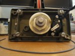
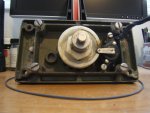
Take a look at these two pictures and tell me which is the correct way the arm and roller should be. When I took the throttle assy apart is was like the first picture with the arm outside of the slot.Neutral Switch 001.jpgNeutral Switch 002.jpg
 

Larry E

Petty Officer 2nd Class
Joined
Jan 1, 2012
Messages
161
Re: Seaswirl manual

Re: Seaswirl manual

Now I am told that the arm is supposed to be spring loaded in the neutral position. Anyone know where I can get one?

Larry E
 
Top